Weider 110 User Manual - Page 7
of the Support Rod 7. Insert the Support Rod
 |
View all Weider 110 manuals
Add to My Manuals
Save this manual to your list of manuals |
Page 7 highlights
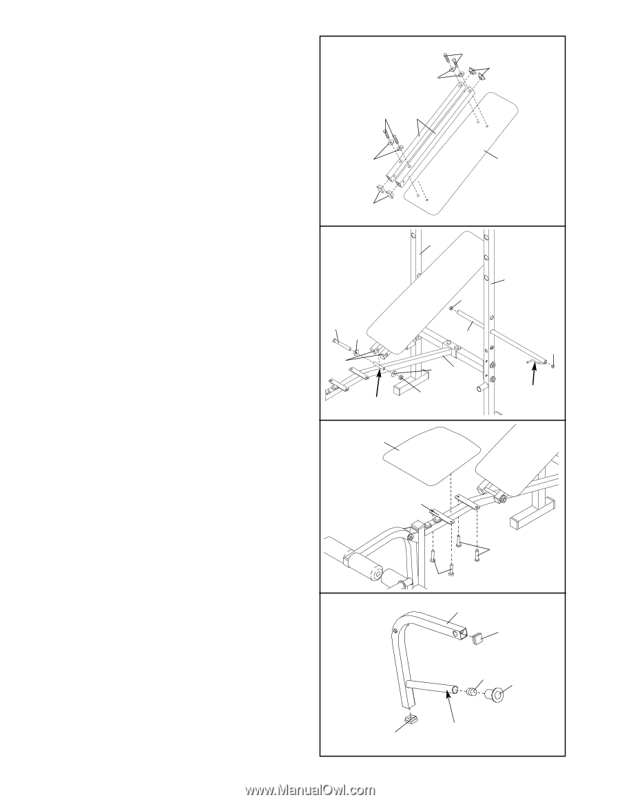
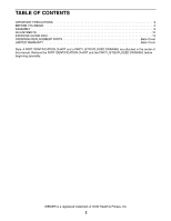
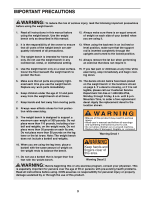
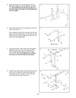
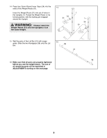
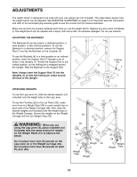
7. Tap two 25mm Square Inner Caps (35) into each of the two Backrest Tubes (5). 7 Attach each Backrest Tube (5) to the Backrest (6) with two M6 x 38mm Screws (30) and two M6 Washers (26). Do not tighten the Screws yet. 30 35 26 30 5 26 6 8. Tap a 19mm Round Inner Cap (9) into each end of the Support Rod (7). Insert the Support Rod into one of the three upper sets of holes in the Uprights (1). Rotate the Support Rod to the locked position, with the locking pin wrapped around the Upright. Note: Always insert the Support Rod into the Uprights so that the locking pin wraps around the back of the Upright. Lubricate the M10 x 135mm Bolt (36) with grease. Attach the Backrest Tubes (5) to the welded tube on the Frame (2) with the Bolt, two M10 Washers (34), and an M10 Nylon Locknut (33). Do not overtighten the Locknut; the Backrest Tubes must be able to pivot easily. Tighten the M6 x 38mm Screws (30) used in step 7, and the Nylon Locknuts (17, 33) used in steps 1 to 3. 9. Attach the Seat (11) to the brackets on the Frame (2) with four M6 x 16mm Screws (29). 35 8 1 9 36 34 7 5 34 2 Welded Tube 33 9 11 2 1 9 Locking Pin 10. Press two 30mm Square Inner Caps (22) into the ends of a Fly Arm (25). Press a 25mm Round 10 Inner Cap (24) into the end of the weight tube. Slide a Weight Stop (28) onto the weight tube. Assemble the other Fly Arm (not shown) in the same manner. 29 29 25 22 24 28 Weight 22 Tube 7
-
 1
1 -
 2
2 -
 3
3 -
 4
4 -
 5
5 -
 6
6 -
 7
7 -
 8
8 -
 9
9 -
 10
10 -
 11
11 -
 12
12 -
13
-
14
-
15
-
16
-
17
-
18
-
19
-
20
 |
 |