Weider 1200 English Manual - Page 5
Part Identification Chart - manual
 |
View all Weider 1200 manuals
Add to My Manuals
Save this manual to your list of manuals |
Page 5 highlights
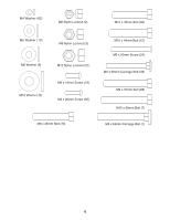
M10 x 198mm Bolt (59) PART IDENTIFICATION CHART Refer to the drawings below to identify small parts used in assembly. The number in parentheses by each drawing is the key number of the part, from the PART LIST near the end of this manual. Note: Some small parts may have been preattached. If a part is not in the hardware kit, check to see if it has been preattached. M6 x 65mm Screw (43) M8 x 67mm Carriage Bolt (86) M10 x 67mm Bolt (11) M10 x 67mm Carriage Bolt (14) M8 x 70mm Bolt (81) M10 x 75mm Bolt (22) M10 x 80mm Bolt (16) M10 x 90mm Bolt (85) M10 x 95mm Bolt (71) M8 x 117mm Bolt (68) 5
-
 1
1 -
 2
2 -
 3
3 -
 4
4 -
 5
5 -
 6
6 -
 7
7 -
 8
8 -
 9
9 -
 10
10 -
 11
11 -
12
-
13
-
14
-
15
-
16
-
17
-
18
-
19
-
20
-
21
-
22
-
23
-
24
 |
 |

M10 x 75mm Bolt (22)
M10 x 67mm Bolt (11)
M10 x 80mm Bolt (16)
M10 x 90mm Bolt (85)
M10 x 198mm Bolt (59)
M8 x 70mm Bolt (81)
M8 x 117mm Bolt (68)
M10 x 67mm Carriage Bolt (14)
M10 x 95mm Bolt (71)
M8 x 67mm Carriage Bolt (86)
M6 x 65mm Screw (43)
5
Refer to the drawings below to identify small parts used in assembly. The number in parentheses by each draw-
ing is the key number of the part, from the PART LIST near the end of this manual.
Note: Some small parts
may have been preattached. If a part is not in the hardware kit, check to see if it has been preattached.
PART IDENTIFICATION CHART