Weider 1200 English Manual - Page 9
Arm Assembly
 |
View all Weider 1200 manuals
Add to My Manuals
Save this manual to your list of manuals |
Page 9 highlights
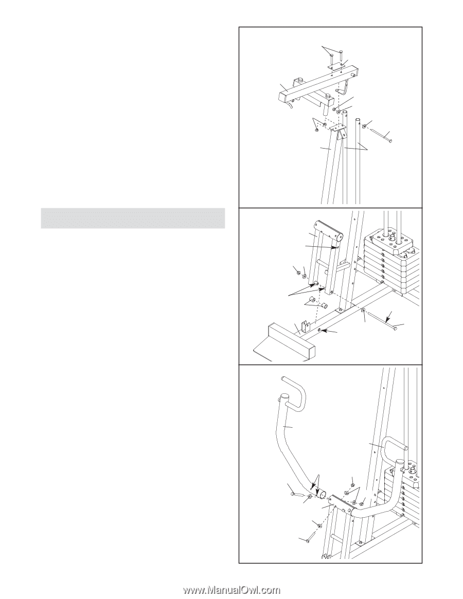
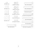
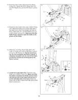
4. Attach the Top Frame (55) to the Front Upright 4 (42) with two M8 x70mm Bolts (81), a Support Plate (84), and two M8 Nylon Locknuts (3). 81 84 Attach the upper ends of the Weight Guides (62) to the Top Frame (55) with an M10 x 155mm Bolt (60), two M10 Washers (9), and an M10 Nylon 55 Locknut (21). 21 Tighten the M8 Nylon Locknuts (3) used in steps 2 and 4. 9 3 9 60 42 62 Arm Assembly 5. Press two 25mm Plastic Bushings (75) onto the welded spacers on the Press Frame (17). Orient the Press Frame so that the hole is in the indicated position. Slide the Press Frame into place on the Base (4) as shown. Note: This will be a tight fit. The Plastic Bushings should fit onto each end of the indicated tube in the Base. Lubricate an M10 x 198mm Bolt (59) with grease. Attach the Press Frame (17) to the Base (4) with the Bolt, two M10 Washers (9), and an M10 Nylon Locknut (21). Do not overtighten the Nylon Locknut; the Press Frame must pivot easily. 6. Identify the Right and Left Press Arms (46, 73) by the position of the indicated holes. Attach the Right Press Arm (46) to the indicated side of the Press Frame (17) with two M10 x 75mm Bolts (22), four M10 Washers (9), and two M10 Nylon Locknuts (21). Assemble the Left Press Arm (73) in the same way. 5 17 Hole 21 9 Welded Spacers 75 4 9 Tube Lubricate 59 6 46 73 Holes 22 9 17 9 22 21 9 21 9
-
 1
1 -
2
-
3
-
 4
4 -
 5
5 -
 6
6 -
 7
7 -
 8
8 -
 9
9 -
 10
10 -
 11
11 -
 12
12 -
 13
13 -
 14
14 -
15
-
16
-
17
-
18
-
19
-
20
-
21
-
22
-
23
-
24
 |
 |