Weider Flex 1000 English Manual - Page 10
Resistance.
 |
View all Weider Flex 1000 manuals
Add to My Manuals
Save this manual to your list of manuals |
Page 10 highlights
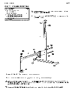
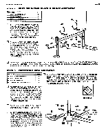
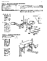
WBDER HEALTH and FITNESS STEP 7 ARM PRESS ASSEMBLY PART NAME QTY 35 5/16* X 3" HEX HEAD BOLT 38 5/16" X 1 3/4" HEX HEAD BOLT 2 13 44 5/16" FLAT WASHER 2 45 5/16' NYLON LOCK NUT 3 57 1" ROUND PLASTIC INSERT CAP 2 64 PLASTIC BUMPER 1 Press 1' ROUND PLASTIC INSERT CAPS (57) Into the ends of the ARM PRESS ARM (12). DETAIL A Assemble the ARM PRESS EXTENSION (13) to the ARM PRESS ARM (12) by inserting the Arm Press Extension Into the welded bracket of the 12 Arm Press Arm. Align the bolt hole locations and bolt with a 5/16" X 1 3/4" HEX HEAD BOLT (38) through the welded bracket of the Arm Press Arm and then through the Arm Press Extension. Secure with 5/16" NYLON LOCK NUTS (45). 14 a 13 76 0 45 1 0 Assemble the ARM PRESS ARM (12) to the top of the UPRIGHT (1) at the long slot location. TO DO THIS, TURN THE ARM PRESS ARM AT AN ANGLE SO THAT THE ARM PRESS EXTENSION AND WELDED SPACER FIT INTO THE OPENING OF THE UPRIGHT FRAME. ONCE INSIDE THE FRAME TUBE, TWIST THE ARM PRESS ARM BACK INTO A STRAIGHT ALIGNMENT. (SEE DETAIL A) Assemble a 5/16' FLAT WASHER (44) onto a 5/16° X 3' HEX HEAD BOLT (35) and bolt the Arm Press assembly to the Upright by bolting through the side of the Upright and then through the welded spacer of the Arm Press Arm. Assemble another 5/16" FLAT WASHER (44) onto the bolt end and secure with a 5/16" NYLON LOCK NUT (45). Attach the PLASTIC BUMPER (64) to the bottom side of the long slot in the UPRIGHT (1) where it comes in contact with the ARM PRESS ARM (12). (SEE DETAIL B) (FOR BEST RESULTS GLUE THE PLASTIC BUMPER). u Remove the ARM PRESS ARM RESISTANCE. __SCALE DECAL (76) (numbers 30 - 110) from the backing sheet and affix over the hole locations on the right side of the Arm Press Arm. Position the '20" at the hole location nearest the Upright. DETAIL B 45 44 13 6 a 12 PAGE 9 38 14 44 35
-
 1
1 -
2
-
3
-
4
-
 5
5 -
 6
6 -
 7
7 -
 8
8 -
 9
9 -
 10
10 -
 11
11 -
 12
12
 |
 |