Weider Flex 1000 English Manual - Page 8
Mounting Bracket Assembly
 |
View all Weider Flex 1000 manuals
Add to My Manuals
Save this manual to your list of manuals |
Page 8 highlights
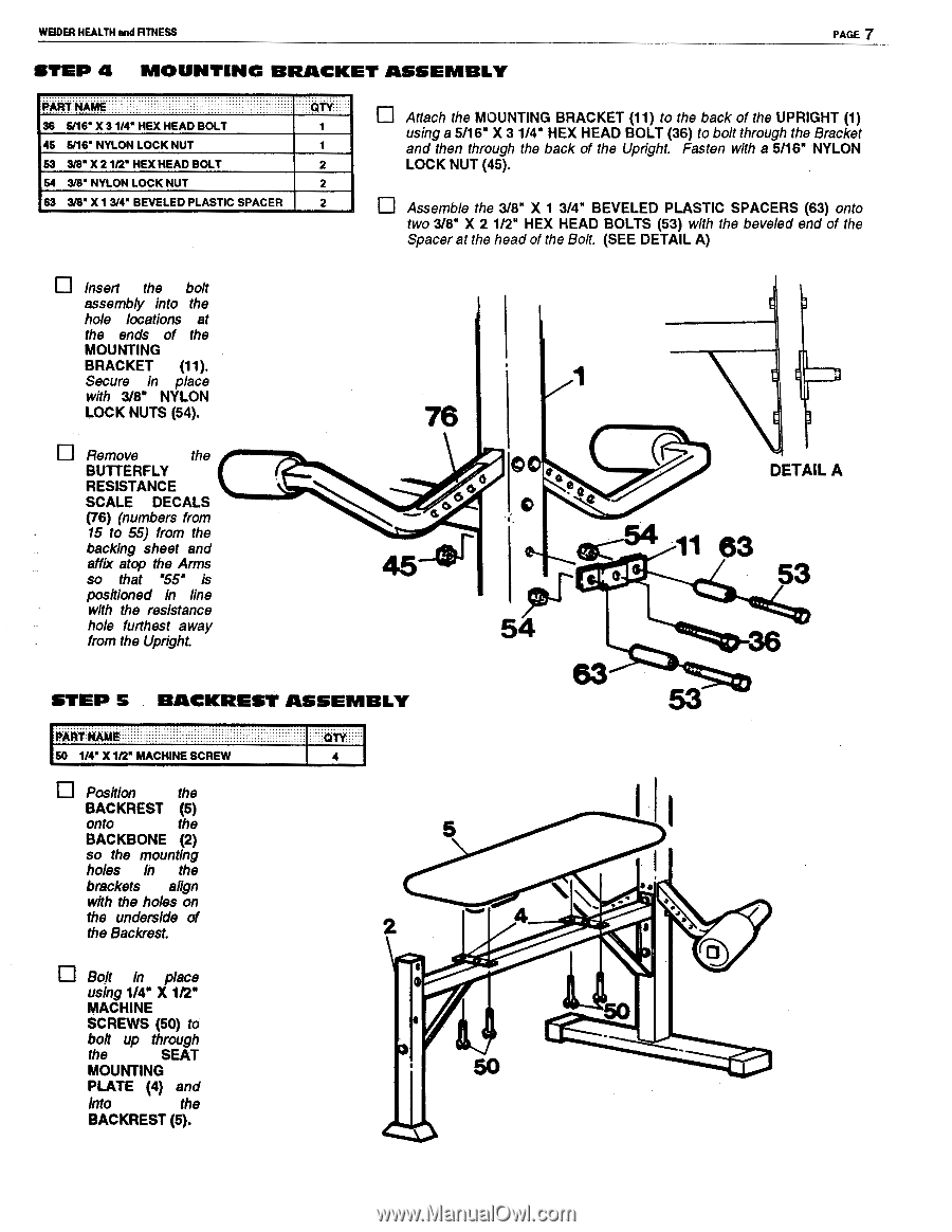
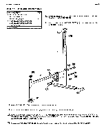
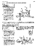
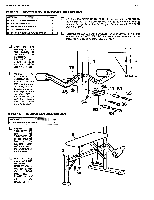
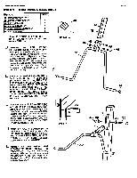
WEIDER HEALTH and FITNESS PAGE 7 STEP 4 MOUNTING BRACKET ASSEMBLY PART NAME ' ' 36 5116" X 31/4" HEX HEAD BOLT 45 5/16' NYLON LOCK NUT 53 3/8" X 21/2" HEX HEAD BOLT 54 3/8' NYLON LOCK NUT 63 3/8" X 1 3/4" BEVELED PLASTIC SPACER QTY ' ' ' 1 1 2 2 2 Attach the MOUNTING BRACKET (11) to the back of the UPRIGHT (1) using a 5/16" X 3 1/4" HEX HEAD BOLT (36) to bolt through the Bracket and then through the back of the Upright. Fasten with a 5/16" NYLON LOCK NUT (45). Assemble the 3/8" X 1 3/4" BEVELED PLASTIC SPACERS (63) onto two 3/8" X 2 1/2" HEX HEAD BOLTS (53) with the beveled end of the Spacer at the head of the Bolt. (SEE DETAIL A) O Insert the bolt assembly into the hole locations at the ends of the MOUNTING BRACKET (11). Secure in place with 3/8" NYLON LOCK NUTS (54). Remove the BUTTERFLY RESISTANCE SCALE DECALS (76) (numbers from 15 to 55) from the backing sheet and affix atop the Arms so that '55" is positioned in line with the resistance hole furthest away from the Upright. 76 45- e r STEP 5 BACKREST ASSEMBLY AO 54 63 DETAIL A 11 63 53 PARrNAME 50 1/4" X 1/2" MACHINE SCREW QTY... 4 Position the BACKREST (5) onto the BACKBONE (2) so the mounting holes In the brackets align with the holes on the underside of the Backrest. Bolt In place using 1/4' X 1/2" MACHINE SCREWS (50) to bolt up through the SEAT MOUNTING PLATE (4) and into the BACKREST (5). • 4 rap • aa
-
 1
1 -
2
-
 3
3 -
 4
4 -
 5
5 -
 6
6 -
 7
7 -
 8
8 -
 9
9 -
 10
10 -
 11
11 -
 12
12
 |
 |