Weider Flex 450 English Manual - Page 22
Stepper, Assembly
 |
View all Weider Flex 450 manuals
Add to My Manuals
Save this manual to your list of manuals |
Page 22 highlights
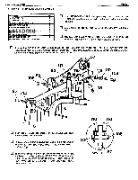
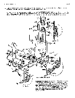
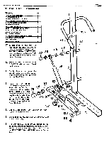
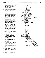
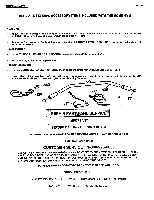
WEIDER HEALTH and FITNESS STEP 18 STEPPER ASSEMBLY . PART NAME 75 11/2" X 3" PLASTIC CAP 77 1" ROUND INSERT CAP 78 1" ROUND PLASTIC COVER CAP 80 5/8' ROUND PLASTIC COVER CAP 81 11/4" SQUARE END BUSHING 84 1' RING RETAINER 85 snr RING RETAINER 88 3/16" X 112" SHEET METAL SCREW 96 6/16' X 1irr HEX HEAD BOLT 104 5/16" FLAT WASHER 105 5/16" NYLON LOCK NUT 117 sir. I.D. FLAIR END SPACER BUSHING 118 5/8" I.D. PLASTIC SPACER 132 TENSION KNOB 133 RUBBER BUMPER QTY 2 2 2 2 4 2 2 2 2 2 2 2 2 2 2 To STEPPER PEDALS (25) and (26) attach RUBBER BUMPERS (133) to the bottom using 3/16" X 1P2 SHEET METAL SCREWS (88). Each Pedal should be turned so that the resistance holes are faced to the center of the unit. 51 118 117 Press 1 1/4" SQUARE END BUSHINGS (81) into each Pedal Pivot Housing. O Double check to be certain the nesewar4 PeVlnle Mrn nn ilk a nresnar sides of frame then press the Pedals onto the Pivot Tube. 28 7\ Press on 1" RING RETAINERS (84) onto Pivot Tube. See illustration 'A' to make certain of the position 78 of the Spring Clip. The teeth must be placed so that they face the outside of the tube. Push the Spring Clip all the way to the Pedal forcing it snugly against the Plastic Bushing. 81 84 96 81 151 0 105 •*\ 132 104 u Cap the ends of the Pivot Tube with 1" R0Uis. PLASTIC COVER CAPS (78). 26 133 Cap ends of PEDALS (25) and (26) with 1 1/2" X 3" PLASTIC CAP (75). 88 .6 Slide 5/8" I.D. FLAIR END SPACER BUSHING (117) all the way onto the support tube, and follow up with a 5/8' I.D. PLASTIC SPACER (118). Next, assemble the RESISTANCE CYLINDER (28) onto the Support Tube. '156 77 135 PAGE 22
-
 1
1 -
2
-
3
-
4
-
5
-
6
-
7
-
8
-
9
-
10
-
11
-
12
-
13
-
14
-
15
-
16
-
 17
17 -
 18
18 -
 19
19 -
 20
20 -
 21
21 -
 22
22 -
 23
23 -
 24
24
 |
 |