Weider Pro 130 User Manual - Page 5
Passembly
 |
View all Weider Pro 130 manuals
Add to My Manuals
Save this manual to your list of manuals |
Page 5 highlights
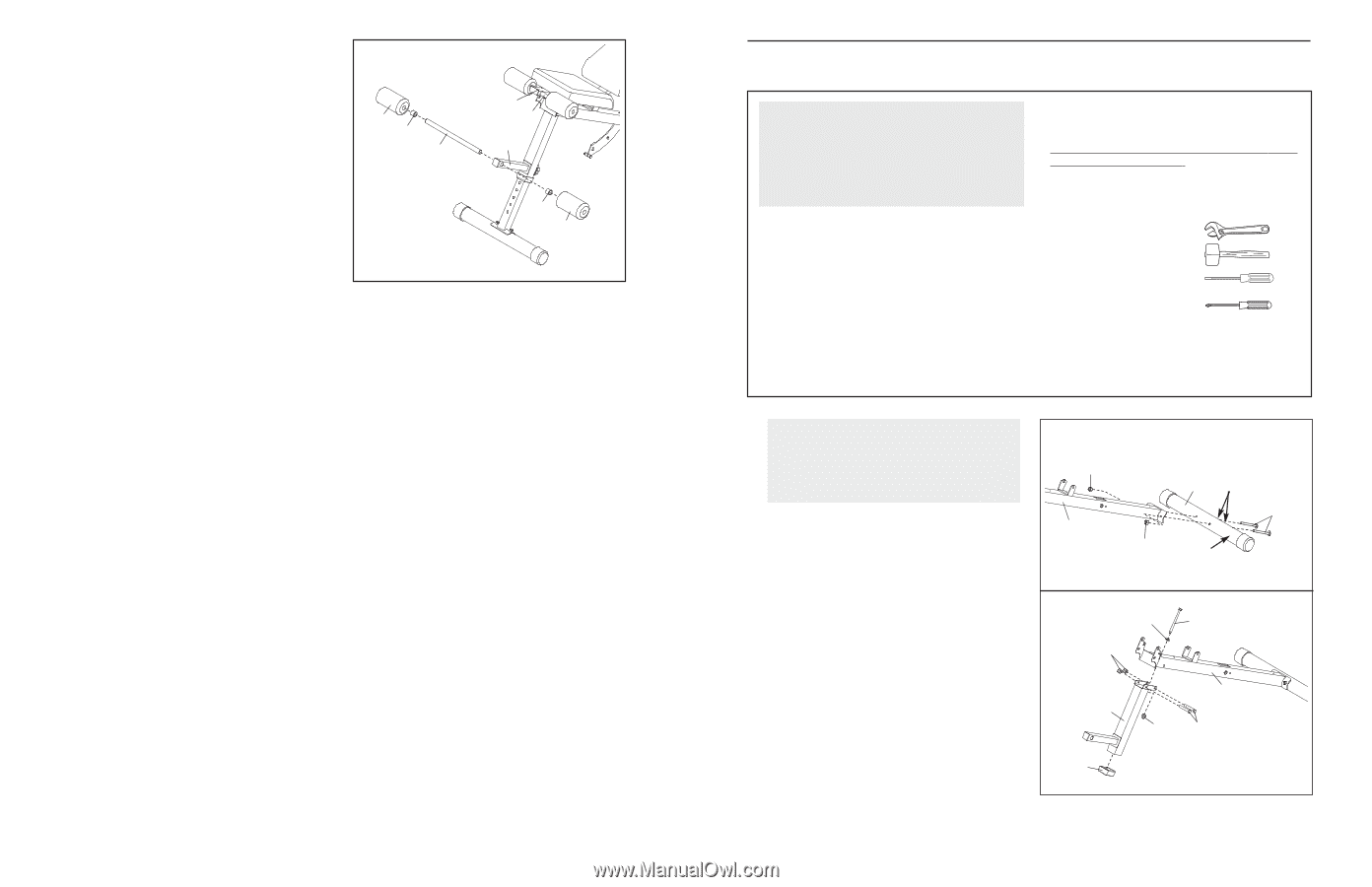
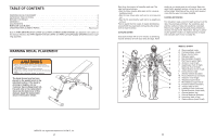
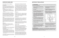
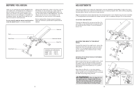
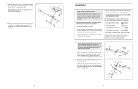
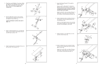
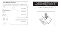
11. Slide the Short Pad Tube (31) through the hole in the Leg (6). Slide two Plastic Spacers (3) and two Foam Pads (11) onto the Pad Tube. Repeat this step with the Long Pad Tube (12) and the Seat Frame (5). 11 11 3 31 12. Make sure that all parts have been properly tightened. The use of the remaining parts will be explained in ADJUSTMENTS, beginning on the next page. 5 12 6 3 11 8 ASSEMBLY Make Things Easier for Yourself Everything in this manual is designed to ensure that the weight bench can be assembled successfully by anyone. Most people find that by setting aside plenty of time, assembly will go smoothly. Before beginning assembly, carefully read the following information and instructions: • Assembly requires two people. • Place all parts in a cleared area and remove the packing materials. Do not dispose of the packing materials until assembly is completed. • Tighten all parts as you assemble them, unless instructed to do otherwise. • As you assemble the weight bench, make sure all parts are oriented as shown in the drawings. • For help identifying small parts, use the PART IDENTIFICATION CHART. The included grease, and the following tools (not included) may be required for assembly: • Two adjustable wrenches • One rubber mallet • One standard screwdriver • One Phillips screwdriver • Clear tape or masking tape, and soapy water. Assembly will be more convenient if you have a socket set, a set of open-end or closed-end wrenches, or a set of ratchet wrenches. 1. Before beginning assembly, make sure you understand the information in the box above. For help identifying small parts, use the PART IDENTIFICATION CHART in the center of this manual. Orient the Stabiliser (2) as shown. Attach the the Bench Frame (1) to the Stabiliser with two M8 x 72mm Carriage Bolts (21) and two M8 Nylon Locknuts (35). Do not tighten the Locknuts yet. 2. Make sure that the Square Bushing (22) is on the end of the Leg (6). Attach the Leg (6) to the Bench Frame (1) with three M8 x 67mm Bolts (34), an M8 Washer (32), and three M8 Nylon Locknuts (35). Do not tighten the Locknuts yet. 1 35 1 Square 2 Holes 21 35 Decal 2 32 34 35 6 22 1 35 34 5
-
 1
1 -
 2
2 -
 3
3 -
 4
4 -
 5
5 -
 6
6 -
 7
7 -
 8
8
 |
 |