Weider Pro 130 User Manual - Page 6
Tighten the M8 Nylon Locknuts 35 used
 |
View all Weider Pro 130 manuals
Add to My Manuals
Save this manual to your list of manuals |
Page 6 highlights
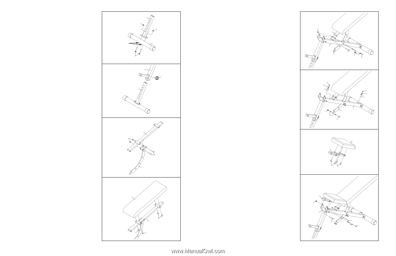
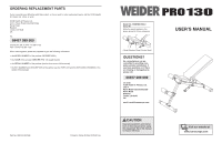
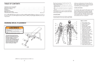
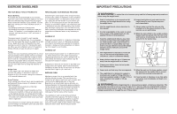
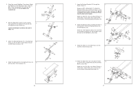
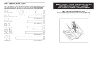
3. Orient the second Stabiliser (2) as shown. Attach 3 the Stabilizer to the Adjustment Leg (7) with two M8 x 72mm Carriage Bolts (21) and two M8 Nylon Locknuts (35). Do not tighten the Locknuts yet. 4. Slide the Adjustment Leg (7) into the Leg (6). 4 Fully tighten the the Adjustment Knob (23) into the Adjustment Leg and the Leg. Tighten the M8 Nylon Locknuts (35) used in steps 1-3. 7 35 35 Square 2 Holes 21 6 23 7 5. Attach the Backrest Bracket (27) to the Backrest 5 Frame (4) with two M10 x 70mm Bolts (19) and two M10 Nylon Locknuts (18). 6. Attach the Backrest (8) to the Backrest Frame (4) 6 with four M6 x 16mm Screws (15). 4 18 19 27 8 15 4 15 15 6 7. Insert the Backrest Bracket (27) through the 7 Bench Frame (1). Grease an M10 x 80mm Bolt (17). Attach the Backrest Frame (4) to the Bench Frame (1) with the Bolt and an M10 Nylon Locknut (18). Do not overtighten the Locknut; the Backrest Frame must be able to pivot easily. Attach the Short Pin (16) to the Bench Frame (1) with an M4 x 12mm Screw (33). Insert the Pin into the Bench Frame and Backrest Bracket (27). 8. Attach two Bumpers (26) to the Bench Frame (1) 8 with two M4 x 16mm Self-tapping Screws (25) and M6 Washers (36). Attach the 10mm Spacers (28) to the round hole in the Backrest Bracket (27) with an M8 x 35mm Bolt (29) and an M8 Nylon Locknut (35). 9. Attach the Seat (9) to the Seat Frame (5) with 9 four M6 x 16mm Screws (15). 18 4 1 27 17 16 33 25 36 26 25 36 26 35 28 27 1 29 9 5 10. Attach the Seat Frame (5) to the Bench Frame (1) with an M10 x 122mm Bolt (20) and an M10 Nylon Locknut (18). Attach the Long Pin (30) to the Bench Frame (1) with an M4 x 12mm Screw (33). Insert the Pin into the Bench Frame and Seat Frame (5). 10 5 18 1 15 15 20 30 33 7
-
 1
1 -
 2
2 -
 3
3 -
 4
4 -
 5
5 -
 6
6 -
 7
7 -
 8
8
 |
 |