Weider Pro 9545 English Manual - Page 10
positioned
 |
View all Weider Pro 9545 manuals
Add to My Manuals
Save this manual to your list of manuals |
Page 10 highlights
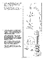
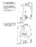
16. Tap a 1" x 1 1/2" Inner Cap (23) into a Handle (26). Tap a 1" Round Cap (22) into the Handle. Apply lubricant to a 3/8" x 2 1/2" Bolt (3). Attach the Handle (26) to the Press Arm (28) with the Bolt and a 3/8" Jam Nut (2). Remove the adhesive backing from a Square Bumper (9). Apply the Square Bumper to the Handle (26) in the indicated location. Assemble the other Handle (26) to the Press Arm (28) in the same manner. 17. IMPORTANT: As you assemble the cables in steps 17 through 30, refer to the CABLE DIAGRAMS on pages 22 and 23, and make sure that the cables are correctly routed. Find the end of the Short Cable (44) where the rubber stop is located. Lay the end of the Cable over a 3 1/2" Pulley (12). Attach the Pulley to the Frame (80) with a 3/8" x 3 3/4" Bolt (83), a 3/8" Flat Washer (4), and a 3/8" Jam Nut (2). Note: Be sure that the Short Cable is between the Pulley and the lat bar bracket. 18. Lay the Short Cable (44) over a 3 1/2" Pulley /1 •IN /A 44.4"1, elakaey.,. D• i,.M •••e..lt./s ,etel "WSJ D • i...I.,/ • /1 'IN %PS V V %el.., I 1.1) to the Frame (80) with the 3/8" x 4 1/2" Bolt (90) and a 3/8" Jam Nut (2). Make sure that the Pulley Covers are turned so the wide tabs are positioned as shown. See step 7. Tighten the 3/8" Jam Nut (2) used in step 7. 16 26 23 2 --.._... ,_ 3-Lubricate 22 26 28 . . 17 83 44 Rubber Stop 12 80 C- -, 6, -&-;-- 4 Lat Bar Bracket \ 2 18 WirlA Tah . 90 13 44 12 Wide Tab 80 . .. 13 19. Assemble the two 4 1/2" Pulley Covers (87), the two "I" Plates (86), and the two 4 1/2" Pulleys (85) with two 3/8" x 1 3/4" Bolts (14) and two 3/8" Jam Nuts (2). 19 14 42 2 87 86 85 p: 86 87 0 ( o .__ 8 2 a 10
-
 1
1 -
2
-
3
-
4
-
 5
5 -
 6
6 -
 7
7 -
 8
8 -
 9
9 -
 10
10 -
 11
11 -
 12
12 -
 13
13 -
 14
14 -
 15
15 -
16
-
17
-
18
-
19
-
20
-
21
-
22
-
23
-
24
-
25
-
26
-
27
-
28
-
29
-
30
-
31
 |
 |
