Weider Pro 9545 English Manual - Page 9
Align
 |
View all Weider Pro 9545 manuals
Add to My Manuals
Save this manual to your list of manuals |
Page 9 highlights
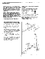
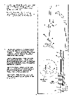
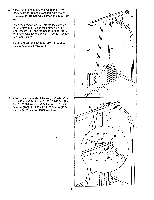
13. Tap two 1 3/4" x 1 3/4" Inner Caps (24) into the Squat Arm (72). Tap two 1" Round Caps (22) into the Squat Arm (72). 13 24 24 22 72 14. Lubricate a 3/8" x 3 1/4" Bolt (5). Attach the Squat 14 Arm (72) to the VKR Upright (70) with the 3/8" x C 3 1/4" Bolt and a 3/8" Jam Nut (2). Do not over- tighten the Jam Nut; the Squat Arm must pivot freely. 72 5 15. Tap two 1 3/4" x 1 3/4" Inner Caps (24) into the uiiCi CiiU L.); tl-IC PICbb AlIII (28). Attach a Rubber Bumper (20) to the Press Arm (28) with a #8 x 1/2" Tap Screw (21). Make sure that there are two 3/4" Flange Bushings (18) in the indicated holes in the Base (43). Press two 3/4" Flange Bushings (18) into the indicated holes in the Press Arm (28). Apply lubricant to the 3/4" x 8 1/2" Axle'(16). Align the bottom of the Press Arm (28) with the 3/4" Flange Bushings (18) in the Base (43). Slide the Axle into the Press Arm and Base. Tap a 3/4" Retainer (17) and a 3/4" Retainer Cap (19) onto each end of the Axle. Note: The teeth on the Retainers must bend toward the Retainer Cap as shown In the inset drawing. 15 19 1 .cl 18 2 -V Lubricate 11 I I I 24 28 20 21 24 ' 4' 16-Lubricate 18 18 43 17 17 16 19 9
-
 1
1 -
2
-
3
-
 4
4 -
 5
5 -
 6
6 -
 7
7 -
 8
8 -
 9
9 -
 10
10 -
 11
11 -
 12
12 -
 13
13 -
 14
14 -
15
-
16
-
17
-
18
-
19
-
20
-
21
-
22
-
23
-
24
-
25
-
26
-
27
-
28
-
29
-
30
-
31
 |
 |
