Weider Pro 9545 English Manual - Page 8
Weider Pro 9545 Manual
 |
View all Weider Pro 9545 manuals
Add to My Manuals
Save this manual to your list of manuals |
Page 8 highlights
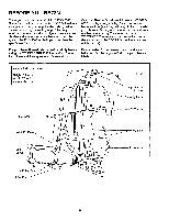
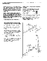
10. Make sure that there are two Long 3/4" Flange Bushings (18) in the indicated side of the Butterfly Arm Frame (42). Tap two 1 3/4" x 1 3/4" Inner Caps (24) into one of the Butterfly Arms (30) as shown. Slide an Adjustment Bracket (32) onto the axle on the Butterfly Arm (30). Turn the Adjustment Bracket so the indicated small hole is on the side shown. Make sure that there is a Short 3/4" Flange Bushing (108) in the Adjustment Bracket, and that the flange of the Bushing is on top. Apply lubricant to the axle on the Butterfly Arm (30). Insert the axle into the indicated hole in the Butterfly Arm Frame (42). Tap two 3/4" Retainers (17) and a 3/4" Retainer Cap (19) onto the end of the axle. Note: The teeth on the Retainers must bend toward the Retainer Cap as shown in the inset drawing. Assemble the other Butterfly Arm (30) and Adjustment Bracket (32) in the same manner. 10 30 19 42 0 o. 32 18 32 108 Small Hole Lubricate 30 24 11. Attach the bent end of a Link Arm (33) to the small hole in one of the Adjustment Brackets (32) with a 3ifs" x 1" Boit (bj, a 3/t3- mastic Washer (34), and a 3/8" Nylon Locknut (27) as shown. Lubricate a 1/4" x 1 114" Bolt (93). Attach the other end of the Link Arm (33) to the Pivot Arm Tube (92) with the 1/4" x 1 1/4" Bolt and a 1/4" Nylon Locknut (68). Attach the other Link Arm (33) to the other Adjustment Bracket (32) in the same manner (not shown). 12. Wet the lower ends of both Butterfly Arms (30) and the insides of the two Long Foam Pads (29) with soapy water. Slide a Long Foam Pad onto each Butterfly Arm. 11 Lubricate 6 93 33 Bent End 92 34N 32 °1I4 68 27 • 30 12 30 30 29 29 8
-
 1
1 -
2
-
 3
3 -
 4
4 -
 5
5 -
 6
6 -
 7
7 -
 8
8 -
 9
9 -
 10
10 -
 11
11 -
 12
12 -
 13
13 -
14
-
15
-
16
-
17
-
18
-
19
-
20
-
21
-
22
-
23
-
24
-
25
-
26
-
27
-
28
-
29
-
30
-
31
 |
 |
