Weider Pro Xt55 English Manual - Page 10
Do not overtighten the Nylon Locknut.
 |
View all Weider Pro Xt55 manuals
Add to My Manuals
Save this manual to your list of manuals |
Page 10 highlights
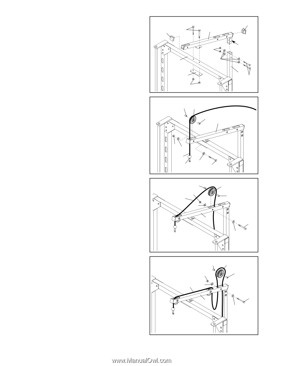
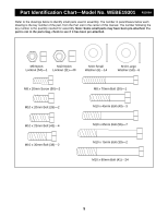
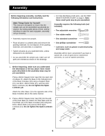
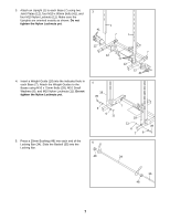
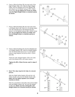
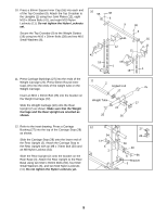
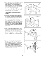
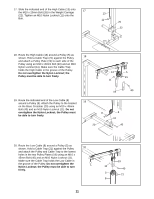
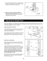
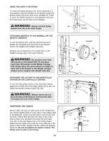
13. Press a 50mm Square Inner Cap (10) into each end of the Pulley Bar (53). Slide the bracket on the Pulley Bar into the top of the Rear Upright (2). Attach the Pulley Bar to the Rear Upright using two M10 x 65mm Bolts (56), four M10 Small Washers (6), and two M10 Nylon Locknuts (11). Attach the Pulley Bar (53) to the Top Crossbar (9) using a Support Plate (57), two M10 x 80mm Bolts (41), and two M10 Nylon Locknuts (11). Tighten all Nylon Locknuts used in steps 1 through 13. 14. Identify the High Cable (13), which is the shorter of the two Cables. Route the High Cable up through the indicated slot in the Pulley Bar (53). Make sure the ball is in the indicated location. Route the High Cable (13) around a Pulley (5) as shown. Attach the Pulley inside the slot in the Pulley Bar (53) using an M10 x 65mm Bolt (56), two M10 Large Washers (58), two Pulley Spacers (15), and an M10 Nylon Locknut (11). Do not overtighten the Nylon Locknut. The Pulley must be able to turn freely. 15. Route the High Cable (13) around another Pulley (5) and through the indicated slot in the Pulley Bar (53) as shown. Attach the Pulley inside the slot using an M10 x 65mm Bolt (56), two M10 Large Washers (58), two Pulley Spacers (15), and an M10 Nylon Locknut (11). Do not overtighten the Nylon Locknut. The Pulley must be able to turn freely. 13 10 41 53 11 9 6 57 11 14 15 5 15 53 10 Bracket 2 56 11 58 13 Ball 58 56 15 15 5 11 13 15 58 53 56 58 16. Route the High Cable (13) up through the Pulley Bar (53), around another Pulley (5), and back 16 through the Pulley Bar, as shown. Attach the Pulley inside the slot in the Pulley Bar using an M10 x 65mm Bolt (56), two M10 Large Washers (58), two Pulley Spacers (15), and an M10 Nylon Locknut (11). Do not overtighten the Nylon Locknut. The Pulley must be able to turn freely. 15 11 13 58 53 5 15 56 58 10
-
 1
1 -
2
-
3
-
4
-
 5
5 -
 6
6 -
 7
7 -
 8
8 -
 9
9 -
 10
10 -
 11
11 -
 12
12 -
 13
13 -
 14
14 -
 15
15 -
16
-
17
-
18
-
19
 |
 |