Weider Pro Xt55 English Manual - Page 9
Rear Base 3. Attach the Rear Upright to the Rear
 |
View all Weider Pro Xt55 manuals
Add to My Manuals
Save this manual to your list of manuals |
Page 9 highlights
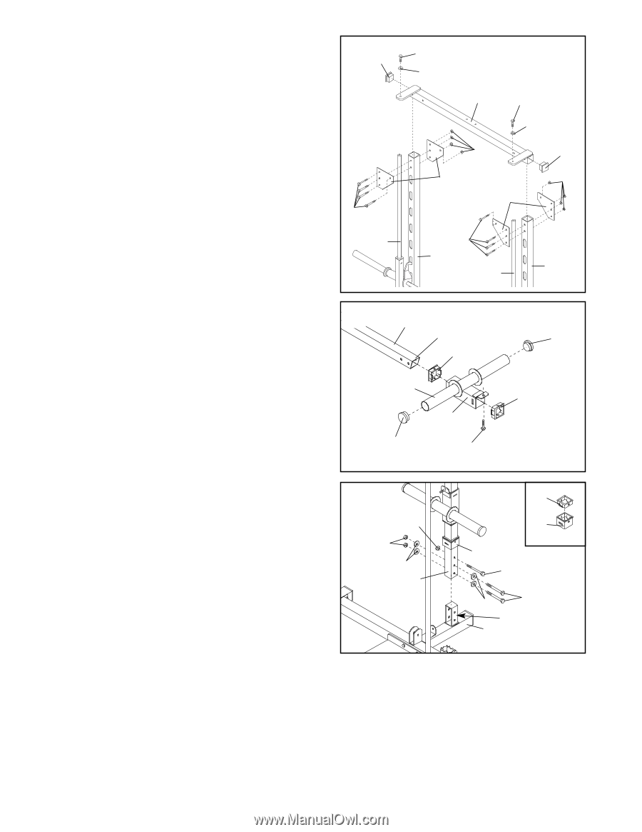
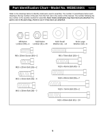
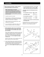
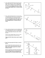
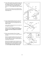
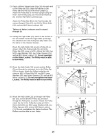
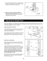
10. Press a 60mm Square Inner Cap (55) into each end of the Top Crossbar (9). Attach the Top Crossbar to the Uprights (1) using four Joint Plates (12), eight M10 x 80mm Bolts (41), and eight M10 Nylon Locknuts (11). Do not tighten the Nylon Locknuts yet. Secure the Top Crossbar (9) to the Weight Guides (18) using two M10 x 30mm Bolts (38) and two M10 Small Washers (6). 10 55 41 18 38 6 9 38 6 11 55 12 11 12 41 1 1 18 11. Press Carriage Bushings (27) into the ends of the Weight Carriage (22). Press 50mm Round Inner Caps (25) into the ends of the weight tube on the Weight Carriage. Insert an M10 x 20mm Bolt (26) into the bracket on the Weight Carriage (22). Slide the Weight Carriage (22) onto the Rear Upright (2) as shown. Make sure that the Weight Carriage and the Rear Upright are oriented as shown. 11 2 Angled End 27 Weight Tube 25 22 26 25 27 12. Refer to the inset drawing. Press a Carriage Bushing (27) into the top of the Carriage Stop (28) as shown. Slide the Carriage Stop (28) onto the lower end of the Rear Upright (2). Attach the Carriage Stop to the Rear Upright with an M8 x 70mm Bolt (30) and an M8 Nylon Locknut (54). Slide the Rear Upright (2) onto the bracket on the Rear Base (3). Attach the Rear Upright to the Rear Base using two M10 x 65mm Bolts (56), four M10 Small Washers (6), and two M10 Nylon Locknuts (11). Do not tighten the Nylon Locknuts yet. 12 54 11 6 2 27 28 28 30 6 56 Bracket 3 9
-
 1
1 -
2
-
3
-
 4
4 -
 5
5 -
 6
6 -
 7
7 -
 8
8 -
 9
9 -
 10
10 -
 11
11 -
 12
12 -
 13
13 -
 14
14 -
15
-
16
-
17
-
18
-
19
 |
 |