Weider Pro Xt55 English Manual - Page 11
Tighten an M10 Nylon Locknut 11 onto
 |
View all Weider Pro Xt55 manuals
Add to My Manuals
Save this manual to your list of manuals |
Page 11 highlights
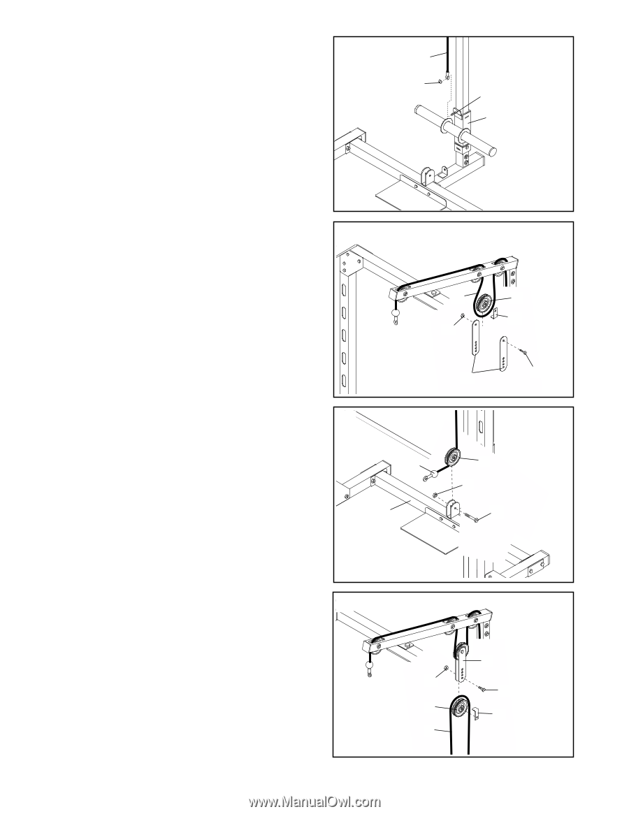
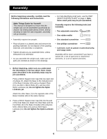
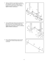
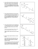
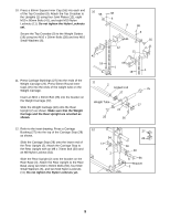
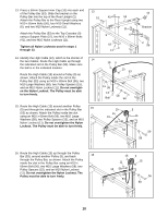
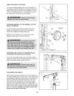
17. Slide the indicated end of the High Cable (13) onto 17 the M10 x 20mm Bolt (26) in the Weight Carriage (22). Tighten an M10 Nylon Locknut (11) onto the Bolt. 13 11 26 22 18. Route the High Cable (13) around a Pulley (5) as shown. Hold a Cable Trap (21) against the Pulley 18 and attach a Pulley Plate (19) to each side of the Pulley using an M10 x 45mm Bolt (40) and an M10 Nylon Locknut (11). Make sure the Cable Trap holds the High Cable in the groove of the Pulley. Do not overtighten the Nylon Locknut; the Pulley must be able to turn freely. 13 5 21 11 19. Route the indicated end of the Low Cable (8) 19 around a Pulley (5). Attach the Pulley to the bracket on the Base Crossbar (20) using an M10 x 45mm Bolt (40) and an M10 Nylon Locknut (11). Do not overtighten the Nylon Locknut; the Pulley must 8 be able to turn freely. 20 19 40 5 11 40 20. Route the Low Cable (8) around a Pulley (5) as shown. Hold a Cable Trap (21) against the Pulley 20 and attach the Pulley and Cable Trap to the lowest holes in the two Pulley Plates (19) using an M10 x 45mm Bolt (40) and an M10 Nylon Locknut (11). Make sure the Cable Trap holds the Low Cable in the groove of the Pulley. Do not overtighten the Nylon Locknut; the Pulley must be able to turn freely. 11 19 11 40 5 21 8
-
 1
1 -
2
-
3
-
4
-
5
-
 6
6 -
 7
7 -
 8
8 -
 9
9 -
 10
10 -
 11
11 -
 12
12 -
 13
13 -
 14
14 -
 15
15 -
 16
16 -
17
-
18
-
19
 |
 |