Weider X2 Uk Manual - Page 9
Arm Assembly
 |
View all Weider X2 manuals
Add to My Manuals
Save this manual to your list of manuals |
Page 9 highlights
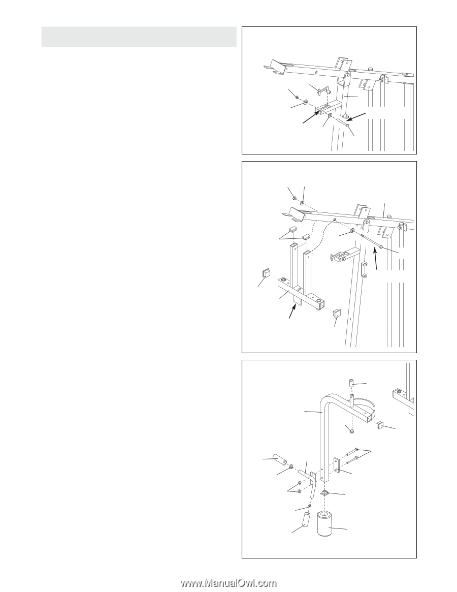
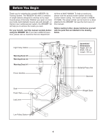
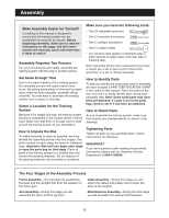
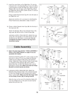
Arm Assembly 8 8. Open the parts bag labelled "ARM ASSEMBLY." Insert the indicated end of the Locking Plate (29) into the slot in the support tube on the Front Upright (4). Lubricate an M10 x 65mm Bolt (58). Attach the Locking Plate to the indicated hole in the support tube with the Bolt, two M10 Flat Washers (62), and an M10 Nylon Locknut (60). 60 29 62 Slot 62 4 Lubricate 58 9. Press two 50mm Square Inner Caps (37) into the 9 Butterfly/Press Frame (9) as shown. Next, press two 25mm x 50mm Inner Caps (39) into the Butterfly/Press Frame (9). 60 62 Lubricate an M10 x 125mm Bolt (51). Attach the Butterfly/Press Frame (9) to the indicated holes in the Top Frame (6) with the Bolt, two 10mm Flat Washers (62), and an M10 Nylon Locknut (60). Make sure 39 62 that the indicated bracket is on the side shown. Do not overtighten the Nylon Locknut; the Butterfly/Press Frame must pivot easily. 37 9 Bracket 37 6 51 Lubricate 10. Press a 45mm Square Inner Cap (38) into each end of the Right Arm (11). Wet the lower end of the Right Arm with soapy water and slide a Short Foam Pad (31) onto the Right Arm. Press a 25mm Round Inner Cap (41) into the indicated hole in the Right Arm (11). Press a 2 3/4" Plastic Sleeve (46) onto the round tube on the Right Arm. Attach the Right Press Handle (20) to the Right Arm (11) with two M8 x 60mm Carriage Bolts (65), a 38mm x 102mm Support Plate (22), and two M8 Nylon Locknuts (70). Press a 25mm Round Inner Cap (41) into each end of the Right Press Handle (20). Slide a 130mm Handgrip (30) onto each end of the Right Press Handle. 10 11 30 20 41 70 41 30 46 41 38 65 22 38 31 9
-
 1
1 -
2
-
3
-
 4
4 -
 5
5 -
 6
6 -
 7
7 -
 8
8 -
 9
9 -
 10
10 -
 11
11 -
 12
12 -
 13
13 -
 14
14 -
15
-
16
-
17
-
18
-
19
-
20
-
21
-
22
-
23
-
24
-
25
 |
 |