Weslo Cadence 200 Instruction Manual - Page 11
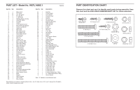
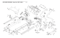
Part List-model No. Wetl14805.1, Part Identification Chart
 |
View all Weslo Cadence 200 manuals
Add to My Manuals
Save this manual to your list of manuals |
Page 11 highlights
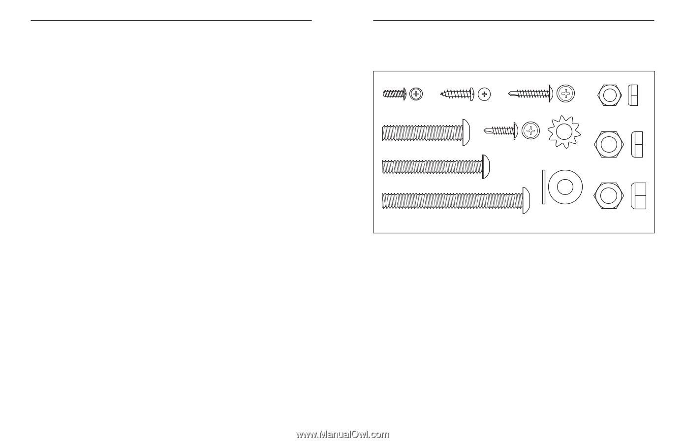
1" Bolt (63)-4 1/4" Star Washer (76)-4 PART LIST-Model No. WETL14805.1 R0905A Key No. Qty. Description Key No. Qty. Description 1 1 Motor Hood 2 13 3/4" Screw 3 16 3/4" Tek Screw 51 52 111/4("3W8)aKC-s4eohyne/sCrolliep BaseWheel Nut (13)-2 53 1 Left Handrail 4 5 8" Cable Tie 54 1 Console Cover 5 4 1" Tek Screw 55 1 Console 6 1 Warning Decal, Console 56 2 3/8" Nut 7 3 Cable Tie Clamp 57 2 Handrail Foam 8 2 Foot Rail 58 F1rame BBolet l(ly70P)a-n2 Grommet 9 4 Isolator 59 1 Right Handrail 10 4 Front Platform Screw 60 1 Wire Harness 11 3 Rear Roller Star Washer 61 4 5/16" Nut 12 2 Incline Leg Washer 62 4 2" Bolt 13 3 14 2 15 4 Wheel Nut Belt Guide Belt Guide Screw 63 4 64 1 65 4 Base Pad Hex Key 2 1/2" Bolt Spacer Screw (45)-2 16 1 Reed Switch Clip 66 8 3/8" Washer 17 1 Reed Switch Screw 67 1 Flywheel 18 2 Hood Anchor 19 1 Drive M5/o1t6o"r Star 68 69 2 1 WSi2lhv"eeBer loGltro(6u4n)d-2Screw 20 2 WireWTaiseher (78)-2 3/8" Star 70 2 3 1/2" Bolt 21 2 Frame U-nut Washer (29)-2 71 2 Plastic Bushing 22 2 Motor Tension Bolt 72 1 Walking Belt 23 1 Motor Isolator Plate 73 1 Belly Pan 24 1 Motor Star Washer 74 1 Walking Board 25 2 26 1 Motor Tension Nut Motor Pivot Bolt 75 1 Large Warning Decal 76 1 Reed SwWitchhe/SeleBnoslotr(6W7i)r-e2 27 2 Frame Spacer 77 1 Drive Roller/Pulley 28 1 Outlet Adapter 78 2 Drive Motor Bolt 29 2 3/8" Star Washer 79 1 Frame 30 1 Power Cord 80 2 Incline Pin 31 1 32 11 Controller Electronic Screw 81 2 Incline Leg 82 23/4" ScIrnecwlin(2e)-L2eg Cap 33 1 Filter 83 1 Right Endcap 34 2 Bracket Grommet 84 1 Console Insert 35 1 Electronics Bracket 85 1 Rear Roller 36 1 37 1 On/Off Switch Circuit Breaker 86 1 Transformer Star Washer (29)-2 # 1 4" Green/Yellow Wire 38 9 Roller Adjustment Washer # 1 8" Red Wire, M/F 39 1 Front Roller Adjustment Bolt # 1 6" Black Wire, M/F 40 2 Plastic Fastener # 1 12" Blue Wire, 2F 41 1 Motor Belt # 1 6" Blue Wire, M/F 42 1 Receptical # 1 8" Blue Wire, 2F 43 2 Rear Roller Adjustment Bolt # 1 4" Black Wire, 2F 44 1 45 2 Latch Pin Assembly Rear Platform Screw # 1 1/4" W8a"sWhehrite Wire, 2F # 1 (38)8-"4Green/Yellow Wire, F/Ring 46 1 Base # 1 10" Green/Yellow Wire, F/Ring 47 1 Magnet # 1 User's Manual 48 1 Latch Housing 49 1 Left Endcap Note: "#" indicates a non-illustrated part. 50 1 Motor Bracket Specifications are subject to change without notice. See the back cover of the user's manual for information about ordering replacement parts. PART IDENTIFICATION CHART Remove this chart and use it to identify small parts during assembly. Save this chart and the EXPLODED DRAWING/PART LIST for future reference. Silver Ground Screw (69)-1 3/4" Screw (2)-12 1" Tek Screw (5)-4 5/16" Nut (61)-4 2" Bolt (62)-4 2 1/2" Bolt (65)-4 3/4" Tek Screw (3)-2 3/8" Star Washer (29)-2 3/8" Nut (56)-2 3 1/2" Bolt (70)-2 3/8" Washer (66)-2 Wheel Nut (13)-2
-
 1
1 -
2
-
3
-
4
-
5
-
 6
6 -
 7
7 -
 8
8 -
 9
9 -
 10
10 -
 11
11 -
 12
12
 |
 |