Weslo Cadence 200 Instruction Manual - Page 9
The SCAN mode
 |
View all Weslo Cadence 200 manuals
Add to My Manuals
Save this manual to your list of manuals |
Page 9 highlights
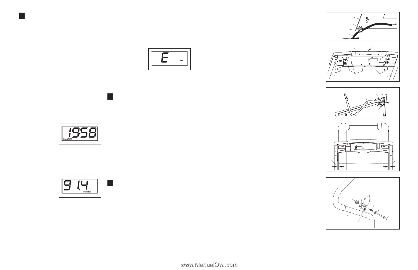
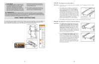
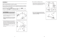
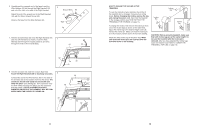
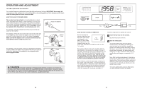
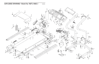
3 Monitor your progress with the display. The display features seven modes: • Time-This mode displays the elapsed time. • Speed-This mode displays the speed of the walking belt. • Distance-This mode displays the distance that you have walked or run. • Calories-This mode displays the approximate number of calories you have burned. • Fat Calories-This mode displays the approximate number of fat calories you have burned (see FAT BURNING on page 18). • Pulse-This mode displays your heart rate when you use the pulse senEsToWr. E14805 (WETL14805) • Scan-This mode displays the time, speed, dis- tance, calories, fat calories, and pulse modes, for a few seconds each, in a repeating cycle. Note: The pulse mode will be displayed only while the pulse sensor is being used. Each time the ETWE14805 (WETL14805) key is inserted into the console, the Scan mode will be selected. The SCAN mode indicator will appear in the display, and a second mode indica- tor will show which mode is currently displayed. Note: If you have selected a different mode, repeatedly press the Display Mode button to rese- lect the scan mode. To select the Time, Speed, Distance, Calories, Fat Calories, or Pulse mode for continuous display, repeatedly press the Display Mode button. The mode indicators will show which mode is selected. Make sure that the SCAN mode indicator does not appear. To reset the displays, press the Stop button, remove the key, and then reinsert the key. Note: The console can display speed and distance in either miles or kilometers (the letters "MPH" or "Km/H" will appear when the Speed mode is displayed). To change the unit of measurement, first hold down the Stop button while inserting the key into the console, and then release the Stop button. An "E" (for English) or an "M" (for metric) will appear in the display. Press the Speed increase button to change the unit of measurement. Then, remove the key and reinsert it. 4 Measure your heart rate if desired. To measure your heart rate, stand on the foot rails and place your thumb on the pulse sensor (see the drawing at the top of page 11). Do not press too hard, or the circulation in your thumb will be restricted and your pulse will not be detected. After a few seconds, the heart-shaped indicator in the display will begin to flash each time your heart beats, one or two dashes will appear, and then your heart rate will be shown. Hold your thumb on the pulse sensor for about 15 seconds for the most accurate reading. If the displayed heart rate appears to be too high or too low, or if your heart rate is not displayed, lift your thumb off the pulse sensor for a few seconds. Then, place your thumb on the pulse sensor as described above. Remember to stand still while measuring your heart rate. 5 When you are finished exercising, remove the key from the console. Step onto the foot rails, press the Stop button, and remove the key from the console. Keep the key in a secure place. Then, switch the on/off switch to the "off" position and unplug the power cord. 12 9. Securely tighten a plastic tie around the Wire Harness (60) and under the indicated hook on the Console (55) to prevent the Wire Harness from slipping. Tighten the plastic tie and cut off the end. See drawing 9a. Set the Console (55) in the Console Base (52). Make sure that the Wire Harness (not shown) is not pinched. Next, set the Console Base on the Handrails (53, 59). Insert as much of the Wire Harness as possible into the hole in the Right Handrail (59). See step 7. Tighten the plastic tie and cut off the end. Loosely thread six 3/4" Screws (2) into the Console Base (52) and the Console (55). Loosely thread four 3/4" Screws into the Handrails (only two Screws are shown). Start all ten Screws and then tighten them; do not overtighten the Screws. 9 55 Hook Tie 60 9a 52 2 59 2 55 2 53 10. Lower the Handrails (53, 59) until they are touching the 10 floor. See 10a. Position the Handrails (53, 59) so the treadmill Frame (79) is centered between them. Firmly tighten the four 2 1/2" Bolts (65), the two 2" Bolts (62), and the two 3 1/2" Bolts (70). Be careful not to overtighten the Bolts. 10a 70 65 53, 59 62 65 79 Top View 59 53 79 11. Orient the Latch Housing (48) so the large hole is on the 11 indicated side. Attach the Latch Housing to the Left Handrail (53) with two 3/4" Screws (2); start both Latch Screws and then tighten them. Remove the knob from the pin. Make sure that the collar and the spring are on the pin. (Note: If there are two collars, place one on each side of the spring.) Next, insert the pin into the Latch Housing (48). Then, tighten the knob back onto the pin. Knob 2 48 Spring Collar Pin 53 Large Hole 12. Make sure that all parts used in assembly are properly tightened before you use the treadmill. Keep the included hex key in a secure place; the hex key is used to adjust the walking belt (see page 17). To protect the floor or carpet, place a mat under the treadmill. 9
-
 1
1 -
2
-
3
-
 4
4 -
 5
5 -
 6
6 -
 7
7 -
 8
8 -
 9
9 -
 10
10 -
 11
11 -
 12
12
 |
 |