Weslo Cadence 200 Instruction Manual - Page 8
Aged When The Power Is Turned On.
 |
View all Weslo Cadence 200 manuals
Add to My Manuals
Save this manual to your list of manuals |
Page 8 highlights
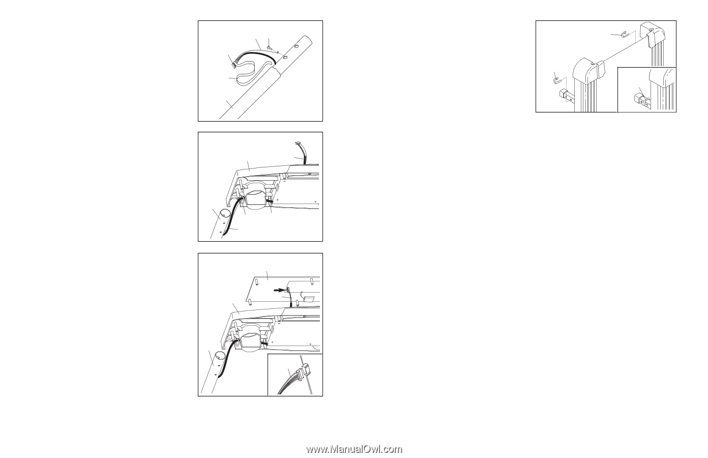
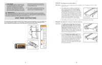
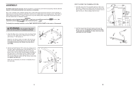
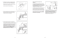
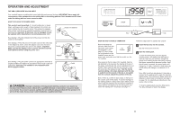
6. Carefully pull the opposite end of the tape to pull the Wire Harness (60) up through the Right Handrail (59) and out of the hole in the side of the Right Handrail. Attach the end of the ground wire to the Right Handrail (59) with the Silver Ground Screw (69). Remove the tape from the Wire Harness (60). 6 Ground Wire 69 60 Tape 59 7. Hold the Console Base (52) near the Right Handrail (59) and the Left Handrail (not shown). Insert the Wire 7 Harness (60) through the looped plastic tie and then through the hole in the Console Base. 52 60 59 Tie 60 60 8. Hold the Console (55) near the Console Base (52). Touch the Right Handrail (59) to discharge any static. 8 Connect the end of the Wire Harness (60) to the back of the Console (55) in the location shown by the arrow. The connector should slide easily into the socket and snap into place (see drawing 8b). If the connector does not slide easily and snap into place, turn the connector 52 and then insert it. IF THE CONNECTOR IS NOT INSERTED PROPERLY, THE CONSOLE MAY BE DAM- AGED WHEN THE POWER IS TURNED ON. 59 55 60 8b 60 8 HOW TO CHANGE THE INCLINE OF THE TREADMILL To vary the intensity of your exercise, the incline of the treadmill can be changed; there are four incline levels. Before changing the incline, remove the key and unplug the power cord. Next, fold the treadmill to the storage position (see HOW TO FOLD THE TREADMILL FOR STORAGE on page 14). To change the incline, first remove the incline pin from one of the incline legs as shown at the right. Next, adjust the incline leg to the desired height, and fully reinsert the incline pin. Make sure that the incline pin is in the "locked" position shown in the inset drawing. Adjust the other incline leg in the same way. Make sure that both incline pins are inserted from the direction shown in the drawing. Incline Pin Incline Pin Incline Pin CAUTION: Before using the treadmill, make sure that both incline legs are at the same height. Do not use the treadmill with the incline pins removed. After you have adjusted the incline legs, lower the treadmill (see HOW TO LOWER THE TREADMILL FOR USE on page 15). 13
-
 1
1 -
2
-
 3
3 -
 4
4 -
 5
5 -
 6
6 -
 7
7 -
 8
8 -
 9
9 -
 10
10 -
 11
11 -
 12
12
 |
 |