Weslo Pursuit 616s Bike English Manual - Page 12
Maintenance
 |
View all Weslo Pursuit 616s Bike manuals
Add to My Manuals
Save this manual to your list of manuals |
Page 12 highlights
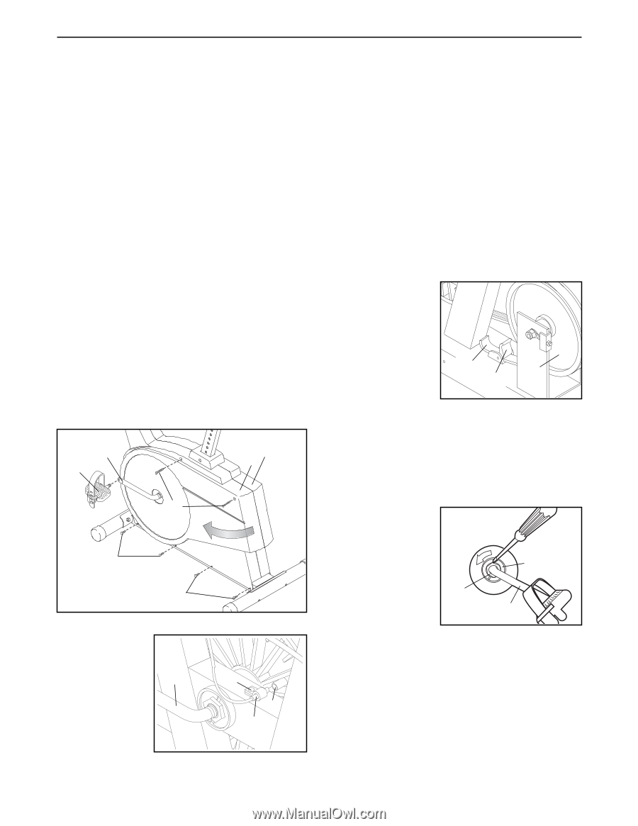
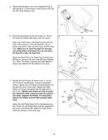
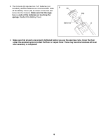
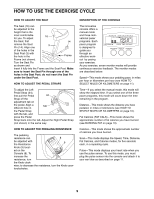
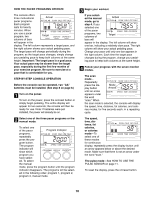
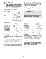
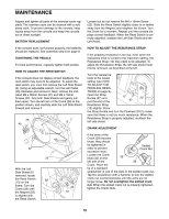
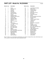
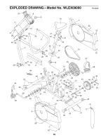
MAINTENANCE Inspect and tighten all parts of the exercise cycle regularly. The exercise cycle can be cleaned with a soft, damp cloth. To prevent damage to the console, keep liquids away from the console and keep the console out of direct sunlight. BATTERY REPLACEMENT If the console does not function properly, the batteries should be replaced. See assembly step 8 on page 8. TIGHTENING THE PEDALS For best performance, regularly tighten both pedals. HOW TO ADJUST THE REED SWITCH If the console does not display correct feedback, the reed switch may need to be adjusted. To adjust the reed switch, you must first remove the Left Side Shield (6). Using an adjustable wrench, turn the Left Pedal (45) clockwise and remove it. Next, remove the indicated M4 x 38mm Screws (21) and M4 x 16mm Screws (22). Grip both Side Shields and gently pull them apart. Turn the left arm of the Crank (29) to the position shown, and carefully slide the Left Side Shield forward and remove it. 29 7 6 45 21 22 22 With the Left Side Shield (6) removed, locate the Reed Switch 29 (13) on the frame. Turn the Crank (29) until the Magnet (23) is aligned with the Reed Switch. 22 23 13 Loosen but do not remove the M4 x 16mm Screw (22). Slide the Reed Switch slightly closer to or farther away from the Magnet, and retighten the Screw. Turn the Crank for a moment. Repeat until the console displays correct feedback. When the Reed Switch is correctly adjusted, reattach the Left Side Shield and the Left Pedal. HOW TO ADJUST THE RESISTANCE STRAP If the pedaling resistance is too low, even when the resistance knob is turned to the maximum setting, the Resistance Strap (12) may need to be adjusted. To adjust the Resistance Strap, the left side shield must first be removed, as described at the left. Turn the resistance knob to the lowest setting (see HOW TO ADJUST THE PEDALING RESIS- TANCE on page 9). Open the Strap Buckle (57) and pull the end of the 12 20 57 Resistance Strap (12) slightly. Close the Strap Buckle and turn the Flywheel (20) to make sure that there is not too much resistance. When the Resistance Strap is properly adjusted, re-attach the left side shield. CRANK ADJUSTMENT If the arms of the Crank (29) become loose, they should be tightened in order to prevent excessive wear. Slotted Crank Nut Loosen the Crank Nuts (35) on the 35 left arm of the 29 Crank. Place the tip of a standard screwdriver in one of the slots in the slotted crank nut. Tap the screwdriver with a hammer to turn the slotted crank nut counterclockwise until the arms are no longer loose. Do not overtighten the slotted crank nut. When the slotted crank nut is properly tightened, tighten the Crank Nuts. 12
-
 1
1 -
2
-
3
-
4
-
5
-
6
-
 7
7 -
 8
8 -
 9
9 -
 10
10 -
 11
11 -
 12
12 -
 13
13 -
 14
14 -
 15
15 -
 16
16
 |
 |