Weslo Pursuit 616s Bike English Manual - Page 6
Connect the Reed Switch Wire 13 to the Extension
 |
View all Weslo Pursuit 616s Bike manuals
Add to My Manuals
Save this manual to your list of manuals |
Page 6 highlights
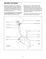
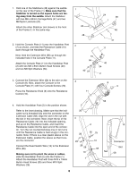
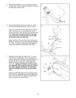
1. Hold one of the Stabilizers (46) against the saddle on the rear of the Frame (1). Make sure that the Stabilizer is turned so the square holes are facing away from the saddle. Attach the Stabilizer with two M8 x 63mm Carriage Bolts (47) and two M8 Nylon Locknuts (24). Attach the other Stabilizer (not shown) to the front of the Frame (1) in the same way. 2. Hold the Console Plate (11) near the Handlebar Post (2) as shown, and feed the Resistance Cable (10) down through the Handlebar Post. Next, feed the Extension Wire (56) up through the indicated hole in the Console Plate (11). Attach the Console Plate (11) to the Handlebar Post (2) with two M6 x 8mm Button Head Screws (40) and two M6 Split Washers (54). 1 24 48 2 10 56 40 54 24 48 1 46 47 11 40 54 2 3. Connect the Extension Wire (56) to the wire on the 3 Console (8). Next, attach the Console to the Console Plate (11) with four Console Screws (20). Press the Resistance Knob (9) onto the Resistance 11 Control (10). 8 9 4. Hold the Handlebar Post (2) in the position shown. Refer to the inset drawing. Make sure that the indicated nut is threaded fully onto the connector on the Extension Cable (58). Align the slot in the nut with the slot in the connector. Next, insert the tip of the Resistance Cable (10) into the indicated opening, pull up on the Resistance Cable, and insert the Resistance Cable into the open end of the connector. Turn the nut counterclockwise one or two turns until the Resistance Cable is held snugly in the connector. Note: If there is a clear plastic sleeve on the Extension Cable, position the sleeve so that it covers the connector Connect the Reed Switch Wire (13) to the Extension Wire (56). Making sure not to pinch the wires or cables, slide the Handlebar Post (2) onto the Frame (1). Attach the Handlebar Post with three M10 x 19mm Button Head Screws (25) and three M10 Split Washers (26). 56 20 4 2 26 26 25 25 26 56 13 1 10 58 Nut 6 10 Connector Slot 58
-
 1
1 -
 2
2 -
 3
3 -
 4
4 -
 5
5 -
 6
6 -
 7
7 -
 8
8 -
 9
9 -
 10
10 -
 11
11 -
 12
12 -
13
-
14
-
15
-
16
 |
 |
