Whirlpool UVL6036JSS Installation Instructions - Page 17
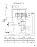
Wiring Diagram
 |
View all Whirlpool UVL6036JSS manuals
Add to My Manuals
Save this manual to your list of manuals |
Page 17 highlights
Junction box N L Gnd BK W R BR Closure temperature: 167°F±5.4°F (75+/-3°C) Opening temperature: ≥140°F (60°C) Temperature sensor W Y Y-G WIRING DIAGRAM SE112A WW W BU R R BK W BK BK BU R R 3 21 7 5 3 1 Fan speed 8 6 4 2 3 21 7 5 3 1 Fan speed 8 6 4 2 R GY W R GY R R W R BK BR On Off 5 3 1 Fan speed 6 4 2 R BK BR BU On Off 5 3 1 Fan 6 4 2 7 21 5 3 Off 1 Light 8 6 4 2 Y W W Y BU Y BU BR BU Speed 1 Speed 2 Speed 3 BU 123456 25uF 25uF 1 2 3 4 5 6 7 8 9 10 BK BK GY GY R W W Y-G BR BR 1 2 345 6 Y/G W R GY BK BU Y Y BR Y W Lamps Optional kit with 1 motor Motor Resistance (Ohms) Motor Characteristics Blue-Red: 18 Blue-White: 21.6 (minimum) Blue-Black: 9.8 (maximum) Power supply: 120 VAC Power absorption: 420 W Blue-Gray: 14.3 Room Temp: 73.4°F (23°C) Frequency: 60 Hz Current: 3.7 A Switch operation with button "1-2-3" Position 1 2 3 Connection 4 2 4 6 5 7 Action Speed 1 Speed 2 Speed 3 Switch operation with button "ON-OFF" Position ON OFF Connection 46 42 Action Motor ON Motor OFF Switch operation with button "Light" Position Connection Action OFF 42 Lights Off 1 46 Low Intensity 2 57 68 High Intensity 17
-
 1
1 -
2
-
3
-
4
-
5
-
6
-
7
-
8
-
9
-
10
-
11
-
 12
12 -
 13
13 -
 14
14 -
 15
15 -
 16
16 -
 17
17 -
 18
18 -
 19
19 -
 20
20 -
 21
21 -
 22
22 -
23
-
24
-
25
-
26
-
27
-
28
-
29
-
30
-
31
-
32
-
33
-
34
-
35
-
36
-
37
-
38
-
39
-
40
 |
 |
