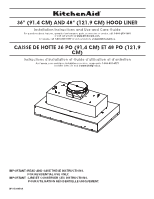
Whirlpool UVL6036JSS Installation Instructions - Page 6
Venting Requirements, Typical Internal Blower Motor System Venting
 |
View all Whirlpool UVL6036JSS manuals
Add to My Manuals
Save this manual to your list of manuals |
Page 6 highlights
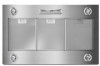
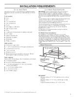
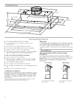
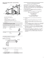
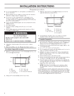
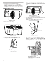
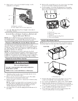
Product Dimensions 123/8" (31.4 cm) 111/2" (29.2 cm) 413/16" (12.2 cm) 51/16" (12.8 cm) 18" (45.7 cm) for 36" models 24" (61.0 cm) for 48" models 27 5/8" (70.1 cm) 2913/16" (75.8 cm) 357/8" (91.1 cm) for 36" models 477/8" (121.6 cm) for 48" models 11" (27.9 cm) 22" (55.9 cm) 101/8" (25.7 cm) Venting Requirements ■ Vent system must terminate to the outdoors. ■ Do not terminate the vent system in an attic or other enclosed area. ■ Do not use 4" (10.2 cm) laundry-type wall caps. ■ Use metal vent only. Rigid metal vent is recommended. ■ Plastic or metal foil vent is not recommended. ■ The length of vent system and number of elbows should be kept to a minimum to provide efficient performance. For the most efficient and quiet operation: ■ Use no more than three 90° elbows. ■ Make sure there is a minimum of 24" (61.0 cm) of straight vent between the elbows if more than one elbow is used. ■ Do not install two elbows together. ■ Use clamps to seal all joints in the vent system. ■ Use caulking to seal exterior wall or roof opening around the cap. ■ The size of the vent should be uniform. Makeup Air Local building codes may require the use of makeup air systems when using ventilation systems greater than specified CFM of air movement. The specified CFM varies from locale to locale. Consult your HVAC professional for specific requirements in your area. Venting Methods Typical Internal Blower Motor System Venting Installations A 10" (25.4 cm) round vent system is needed for installation (not included). The hood exhaust opening is 10" (25.4 cm) round. NOTE: Flexible vent is not recommended. Flexible vent creates back pressure and air turbulence that greatly reduce performance. Roof Venting Wall Venting B A A B Cold Weather Installations An additional back draft damper should be installed to minimize backward cold air flow and a thermal break should be installed to minimize conduction of outside temperatures as part of the vent system. The damper should be on the cold air side of the thermal break. The break should be as close as possible to where the vent system enters the heated portion of the house. A. 10" (25.4 cm) round vent B. Roof cap A. 10" (25.4 cm) round vent B. Wall cap 6
-
 1
1 -
 2
2 -
 3
3 -
 4
4 -
 5
5 -
 6
6 -
 7
7 -
 8
8 -
 9
9 -
 10
10 -
 11
11 -
 12
12 -
13
-
14
-
15
-
16
-
17
-
18
-
19
-
20
-
21
-
22
-
23
-
24
-
25
-
26
-
27
-
28
-
29
-
30
-
31
-
32
-
33
-
34
-
35
-
36
-
37
-
38
-
39
-
40
 |
 |
