Whirlpool UVL6036JSS Installation Instructions - Page 5
INSTALLATION REQUIREMENTS, Tools and Parts
 |
View all Whirlpool UVL6036JSS manuals
Add to My Manuals
Save this manual to your list of manuals |
Page 5 highlights
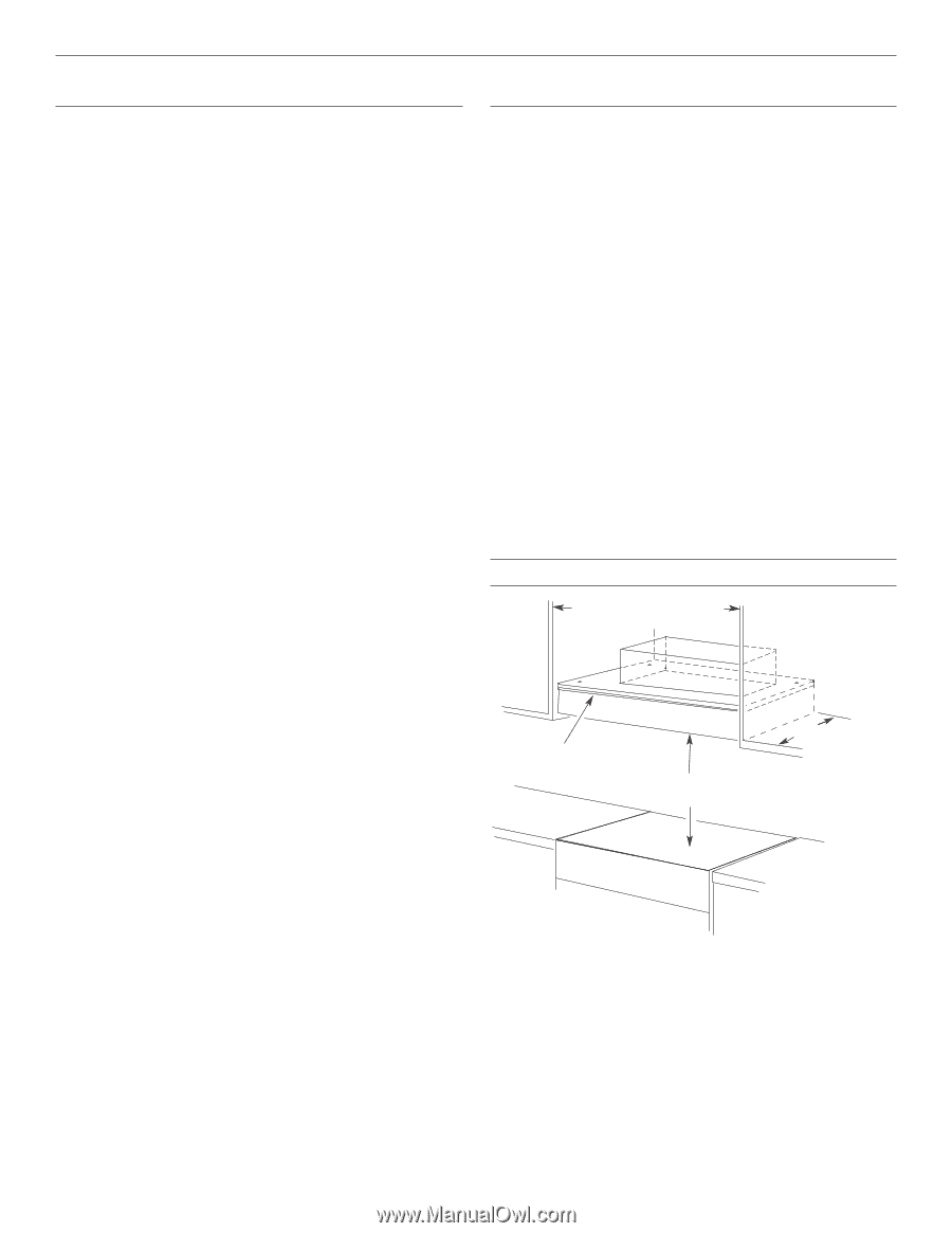
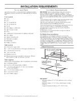
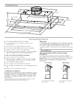
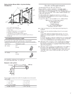
INSTALLATION REQUIREMENTS Tools and Parts Gather the required tools and parts before starting installation. Read and follow the instructions provided with any tools listed here. Tools needed ■ Level ■ Drill ■ 11/4" (3 cm) drill bit ■ 1/8" (3 mm) drill bit ■ Pencil ■ Wire stripper or utility knife ■ Tape measure or ruler ■ Pliers ■ Caulking gun and weatherproof caulking compound ■ Vent clamps ■ Jigsaw or keyhole saw ■ Flat-blade screwdriver ■ Metal snips ■ Phillips screwdriver Parts needed ■ Home power supply cable ■ 1 - 1/2" (13 mm) UL listed or CSA approved strain relief ■ 3 UL listed wire connectors ■ 1 wall or roof cap ■ Metal vent system ■ Blower motor system - internal or external (see "Blower Motor System" in the "Accessories" section). Parts supplied Remove parts from packages. Check that all parts are included. ■ 3 metal grease filters ■ Hood liner with halogen lamps installed. ■ 1 - 10" (25.4 cm) square to 10" (25.4 cm) round duct transition with damper. ■ 4 - 5 x 45 mm mounting screws ■ 4 - 4.2 x 8 mm screws ■ T-20® TORX®† adapter Location Requirements IMPORTANT: Observe all governing codes and ordinances. Have a qualified technician install the hood liner. It is the installer's responsibility to comply with installation clearances specified on the model/serial rating plate. The model/serial rating plate is located behind the left filter on the rear wall of the hood liner. The hood liner location should be away from strong draft areas, such as windows, doors, and strong heating vents. Cabinet opening dimensions that are shown must be used. Given dimensions provide minimum clearance. The hood liner must be surrounded by a custom built enclosure with hood support capable of supporting 75 lb (34 kg). Grounded electrical outlet is required. See the "Electrical Requirements" section. All openings in ceiling and wall where canopy hood will be installed must be sealed. For Mobile Home Installations The installation of this range hood must conform to the Manufactured Home Construction Safety Standards, Title 24 CFR, Part 328 (formerly the Federal Standard for Mobile Home Construction and Safety, Title 24, HUD, Part 280) or when such standard is not applicable, the standard for Manufactured Home Installation 1982 (Manufactured Home Sites, Communities and Setups) ANSI A225.1/NFPA 501A, or latest edition, or with local codes. Cabinet Dimensions 36" (91.4 cm) for 36" models 48" (121.9 cm) for 48" models Hood support must be capable of supporting 75 lb (34 kg) "X" bottom of canopy to cooking surface 22" (55.9 cm) Hood liner depth IMPORTANT: Minimum distance "X": 24" (61 cm) from electric cooking surfaces. Minimum distance "X": 30" (76.2 cm) from gas cooking surfaces. Suggested maximum distance "X": 36" (91.4 cm). †®TORX and T20 are registered trademarks of Acument Intellectual Properties, LLC. 5
-
 1
1 -
 2
2 -
 3
3 -
 4
4 -
 5
5 -
 6
6 -
 7
7 -
 8
8 -
 9
9 -
 10
10 -
 11
11 -
12
-
13
-
14
-
15
-
16
-
17
-
18
-
19
-
20
-
21
-
22
-
23
-
24
-
25
-
26
-
27
-
28
-
29
-
30
-
31
-
32
-
33
-
34
-
35
-
36
-
37
-
38
-
39
-
40
 |
 |