Whirlpool UVL6036JSS Installation Instructions - Page 8
INSTALLATION INSTRUCTIONS, Prepare Location, WARNING
 |
View all Whirlpool UVL6036JSS manuals
Add to My Manuals
Save this manual to your list of manuals |
Page 8 highlights
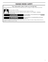
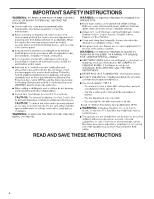
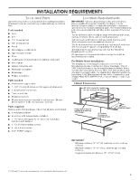
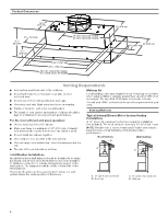
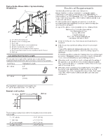
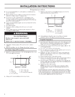
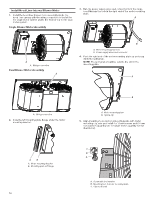
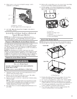
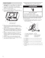
INSTALLATION INSTRUCTIONS Prepare Location ■ It is recommended that the vent system be installed before hood is installed. 3. Mark the cutout for the rectangular clearance hole for the upper hood liner housing as shown. ■ Before making cutouts, make sure there is proper clearance within the ceiling or wall for exhaust vent. ■ Hood liner is to be installed 24" (61.0 cm) minimum for electric cooking surfaces, 30" (76.2 cm) minimum for gas cooking surfaces, to a suggested maximum of 36" (91.4 cm) above the cooking surface. ■ Check that all installation parts have been removed from the shipping carton. 1. Disconnect power. 2. Determine which venting method to use: roof or wall exhaust. 3. Select a flat surface for assembling the range hood. Place covering over that surface. WARNING A B C D G E F A. Wall B. Centerline C. 41/2" (11.4 cm) D. 13" (33.0 cm) E. 14" (35.5 cm) F. 28" (71.1 cm) G. Hood support Excessive Weight Hazard Use two or more people to move and install range hood. Failure to do so can result in back or other injury. 4. Using two or more people, lift hood liner onto covered surface. 5. Remove the filters. See the "Range Hood Care" section. Hood Liner Support Preparation 1. Mark the locations for the four 1/8" (3 mm) diameter holes on the hood support as shown. A B C G D E F A. Wall B. Centerline C. 6" (15.2 cm) D. 101/8" (25.7 cm) E. 1415/16" (38.0 cm) F. 2913/16" (75.8 cm) G. 1/8" (3 mm) hole diameter 4. Using a jigsaw or keyhole saw, cut out the rectangular clearance hole for the upper hood liner housing. Complete Preparation 1. Determine and make all necessary cuts in the wall or roof for the vent system. Install the vent system before installing the range hood. See the "Venting Requirements" section. 2. Determine the location where the power supply cable will be run through the wall. 3. Drill a 11/4" (3.2 cm) hole at this location. 4. Pull enough power supply cable through the wall to allow for easy connection to the terminal box. 5. Install the 10" (25.4 cm) square x 10" (25.4 cm) round vent transition with damper to top of the range hood liner using four 4.2 x 8 mm screws. 6. Remove terminal box cover and set aside. 7. Remove knockout from the top of the vent hood and install a UL listed or CSA approved 1/2" (13 mm) strain relief. 8. Place the range hood near its mounting position and run the power supply cable through the strain relief into terminal box (enough to make connection). 9. Tighten the strain relief screws. NOTE: Your range hood requires you to purchase either an internal type or an in-line (external type) blower motor system. For internal blower systems, there are blower motor mounting parts in the blower motor installation packet that must be added to the range hood prior to mounting the range hood to the wall. See the "Install Range Hood Internal Blower Motor" section and the instructions supplied with the blower motor. 2. Using a 1/8" (3 mm) drill bit, drill the four holes. 8
-
 1
1 -
2
-
 3
3 -
 4
4 -
 5
5 -
 6
6 -
 7
7 -
 8
8 -
 9
9 -
 10
10 -
 11
11 -
 12
12 -
 13
13 -
14
-
15
-
16
-
17
-
18
-
19
-
20
-
21
-
22
-
23
-
24
-
25
-
26
-
27
-
28
-
29
-
30
-
31
-
32
-
33
-
34
-
35
-
36
-
37
-
38
-
39
-
40
 |
 |