Yamaha CL3 Cl Editor Owner's Manual
Yamaha CL3 Manual
 |
View all Yamaha CL3 manuals
Add to My Manuals
Save this manual to your list of manuals |
Yamaha CL3 manual content summary:
- Yamaha CL3 | Cl Editor Owner's Manual - Page 1
displays as illustrated in this owner's manual are for instructional purposes, and may appear somewhat different from the screens which appear on your computer. • For information on modification of system software, certain functions, or specifications due to version update of the application, please - Yamaha CL3 | Cl Editor Owner's Manual - Page 2
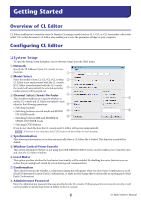
Started Overview of CL Editor CL Editor enables you to remotely control a Yamaha CL mixing console (such as CL5, CL3, or CL1; hereinafter collectively called "CL" in this document). CL Editor also enables you to save the parameter settings on your computer. Configuring CL Editor ❏ System Setup - Yamaha CL3 | Cl Editor Owner's Manual - Page 3
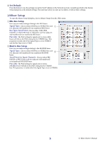
you start up CL Editor, it will use these settings. ❏ Mixer Setup To open the Mixer Setup dialogbox, choose [Mixer Setup] from the [File] menu. 1 Mix Bus Setup Here you can make settings relating to the MIX buses. Signal is valid only if the Signal Type is set to STEREO. 3 CL Editor Owner's Manual - Yamaha CL3 | Cl Editor Owner's Manual - Page 4
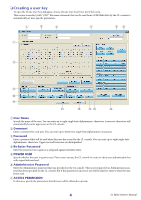
by the CL console to automatically set user-specific parameters. 1 CL console, but if this password is incorrect you will be asked to enter it when the user key is read. 7 ACCESS PERMISSION In this area, specify the parameters that this user will be allowed to operate. 4 CL Editor Owner's Manual - Yamaha CL3 | Cl Editor Owner's Manual - Page 5
D SYSTEM SETUP MIXER SETUP: Change the privileges for making mixer setup settings. OUTPORT SETUP: Change the privileges for making outport setup settings. MIDI: Change the privileges for making MIDI settings. E Create Creates the user key. F Cancel Closes the dialogbox. 5 CL Editor Owner's Manual - Yamaha CL3 | Cl Editor Owner's Manual - Page 6
name Quitting the CL Editor Choose CL console data is saved (filename extension ".CLF") can also be handled, allowing you to use a USB flash drive to exchange data with the CL console. Undo/Redo Function In CL to use the CL console • Synchronizing with the CL console available only using the [ - Yamaha CL3 | Cl Editor Owner's Manual - Page 7
the editor. ● Tile ● Cascade In the Library window or Scene window, click the tabs located at the top of the window to switch between pages. 7 CL Editor Owner's Manual - Yamaha CL3 | Cl Editor Owner's Manual - Page 8
not available. 2 Select whether you want to transfer your settings to CL Editor, or vice versa. At this time, the All Libraries option determines whether or not Library data is synchronized. Console ➔ key to set the nominal value regardless of the default value. 8 CL Editor Owner's Manual - Yamaha CL3 | Cl Editor Owner's Manual - Page 9
in the System Setup dialog box is selected, this parameter is linked with the [SEL] buttons on the CL console panel. You can right-click ( key + click) the icon to select a different one. You can linked with the SENDS ON FADER mode setting on the CL console. 9 CL Editor Owner's Manual - Yamaha CL3 | Cl Editor Owner's Manual - Page 10
[Re-Synchronize]. (➥ p.8) NOTE If CL Editor is in the offline status the [Re-synchronize] function is not available. ❏ SCENE MEMORY Here you can view on the CL. 6 [RECALL] button This button recalls the scene of the number shown in the scene number display (1). 4 10 CL Editor Owner's Manual - Yamaha CL3 | Cl Editor Owner's Manual - Page 11
CH 33-48 window. 4 [49-64] button Opens the INPUT CH 49-64 window (only CL5/CL3.) 5 [65-72] button Opens the INPUT CH 65-72 window (only CL5.) 6 [ST IN] button Opens the ST IN window. 7 [DCA] button Opens the DCA (Digital-Controlled Amplifier) window. 890A OUTPUT 8 [1-16] button Opens the MIX CH - Yamaha CL3 | Cl Editor Owner's Manual - Page 12
window This window displays the mix parameters of INPUT CH 1-16, 17-32, 33-48, 49-64 (only CL3/CL5), or 65-72 ( choose [Overview] and select CH 1-16, 17-32, 33-48, 49-64 (only CL3/CL5), or 65-72 (only CL5) • Use the bank select keys in the Master window to turn on the . 12 CL Editor Owner's Manual - Yamaha CL3 | Cl Editor Owner's Manual - Page 13
Digital Gate is assigned, a GR meter is shown immediately below the MIX/MATRIX (MIX/MATRIX SEND) Switches between the send indications to MIX CH to VARI type MIX/MATRIX buses. You can the INPUT CH to the MIX/MATRIX buses. Pre/on ( bar graph. NOTE For FIXED-type MIX buses, the bar graph is fixed - Yamaha CL3 | Cl Editor Owner's Manual - Page 14
show the Recall Safe and Mute Safe status of the channel. Mute Group indicator DCA Group indicator Level Meter The numbers of mute groups to which this channel belongs are shown in red when those groups are name. You can also edit the channel name in this text box. 14 CL Editor Owner's Manual - Yamaha CL3 | Cl Editor Owner's Manual - Page 15
window you can view and edit the mix parameters of ST IN channels 1-8. The 7 4 Ø (Phase) Inverts the phase polarity of the signal after AD conversion. 5 Digital Gain Drag the knob in the screen to adjust the input gain to each ST IN channel. for INPUT CH (➥ p.13.) 15 CL Editor Owner's Manual - Yamaha CL3 | Cl Editor Owner's Manual - Page 16
MIX/MATRIX (MIX/MATRIX SEND) Switches between the send indications to MIX buses 1-24 or to MATRIX buses 1-8. This is the same as the mix/ switch between 3 indicators (mute group indicator, DCA group indicator, level meter). F Channel number This is the number of the ST IN CL Editor Owner's Manual - Yamaha CL3 | Cl Editor Owner's Manual - Page 17
will be assigned to the MIX channel, from the fol- 2 lowing choices. NONE No assignment DANTE 1-DANTE 64 DANTE OUTPUT 1-64 OMNI 1-OMNI of PREMIUM rack 1-2 DIGI L, DIGI R L/R channels of the DIGITAL OUT jack If multiple patches have been made, only the first port 17 CL Editor Owner's Manual - Yamaha CL3 | Cl Editor Owner's Manual - Page 18
channel and even- 0 numbered channel. The stereo bus setting can be made in Mix Bus Setup of the Mixer Setup dialogbox. The [ST] button is an on/off switch for the signal that is sent from down the (< >) key and key and clicking the fader knob. 18 CL Editor Owner's Manual - Yamaha CL3 | Cl Editor Owner's Manual - Page 19
Recall Safe indicator Level Meter This level meter is displayed at the same metering point with the input channel in Meter window setup (➥ p.67 White: You can adjust the input level of the MIX channel (normal mode.) Gray: MIX channel is off. Other colors: You can adjust CL Editor Owner's Manual - Yamaha CL3 | Cl Editor Owner's Manual - Page 20
" • Use the bank select keys in the Master window to turn on the [MTRX] button 1 1 MIX/CH/ST IN (Send levels from the MIX/INPUT CH/ST IN to the MATRIX bus) This switches between indicating the sends from MIX channels 1-24, the sends from INPUT CH 1-16/17-32/33-48/49-64 (CL3), 49 - Yamaha CL3 | Cl Editor Owner's Manual - Page 21
meaning of the display 3 are the same as for (5) MATRIX in the MIX window (➥ p.18.) 3 EQ (Equalizer) Switches the EQ on/off. indicators (mute group indicator, mute safe/recall safe indicator, level meter). 0 Channel number Indicates the number of the MATRIX channel. CL Editor Owner's Manual - Yamaha CL3 | Cl Editor Owner's Manual - Page 22
window in the following ways. • From the [Windows] menu, choose [Overview] and then choose "STEREO/MONO" • Use the bank select keys in the Master window to turn on the [ST] button 1 1 EQ (Equalizer) Switches the are the same as for MATRIX in the MIX window (➥ p.18.) 22 CL Editor Owner's Manual - Yamaha CL3 | Cl Editor Owner's Manual - Page 23
side of the fader to switch between 3 indicators (mute group indicator, mute safe/recall safe indicator, level meter). 0 Channel number This is the channel number (ST or M.) You can double-click this number to name. You can also edit the channel name in this text box. 23 CL Editor Owner's Manual - Yamaha CL3 | Cl Editor Owner's Manual - Page 24
is a text box that displays the DCA group name. You can also edit the DCA group name in this text box. 6 Level Meter This level meter indicates the post-meter of DCA. 6 NOTE Click the level meter area to switch between the recall-safe indicator and the level meter. 24 CL Editor Owner's Manual - Yamaha CL3 | Cl Editor Owner's Manual - Page 25
not linked with [SEL] button operations on the panel of the CL. The type of parameters that can be edited in this window depends MIX channels 1-24, MATRIX channels 1-8, and STEREO/MONO channels.) (*) CL3: 1-64, CL1: 1-48 If an input channel is selected ● INPUT CH window 25 CL Editor Owner's Manual - Yamaha CL3 | Cl Editor Owner's Manual - Page 26
window NOTE Unless otherwise specified, the parameters explained below are common to INPUT CH 1-72 (CL3: 1-64, CL1: 1-48) and ST IN channels 1-8. ❏ CHANNEL SELECT (Channel selection) 2 1 3 1 SELECT to the input channel (for the selectable input sources, ➥ p.12.) 26 CL Editor Owner's Manual - Yamaha CL3 | Cl Editor Owner's Manual - Page 27
in the Mixer Setup dialogbox. 4 Channel name This section indicates the name of the MIX channel or CL consoles, this function maintains the audio signal at a specific level throughout the network. This button will be displayed only if the DANTE ports have been patched. 27 CL Editor Owner's Manual - Yamaha CL3 | Cl Editor Owner's Manual - Page 28
[PAN]/[BALANCE] buttons. CSR (Center Side Ratio) Adjusts the proportion of the CENTER channel level relative to the STEREO bus L/R in a range of 0-100%. 28 CL Editor Owner's Manual - Yamaha CL3 | Cl Editor Owner's Manual - Page 29
) Selects either TYPE I or TYPE II as the EQ type. A ATT (Attenuation) Adjusts the amount of attenuation for the signal level of pre EQ. 29 CL Editor Owner's Manual - Yamaha CL3 | Cl Editor Owner's Manual - Page 30
Indicates the response for the gate/ducking of the currently selected channel. 5 GR meter (Gain Reduction meter) This meter indicates the amount of gain reduction produced by the gate/ducking. 6 THRESH (Threshold ) after the key-in signal falls below the threshold. 30 CL Editor Owner's Manual - Yamaha CL3 | Cl Editor Owner's Manual - Page 31
MIX CH41-48, CH49- compression will be removed when the signal falls below this level. If the expander is selected, the input signal will start being compressed when the key-in signal falls below this level; compression will be removed when the signal exceeds this level. 31 CL Editor Owner's Manual - Yamaha CL3 | Cl Editor Owner's Manual - Page 32
selected channel. 5 GR meter (Gain Reduction meter) This meter indicates the amount of compression and expansion are applied. The input signal will be compressed when the key-in signal exceeds this level. The expander effect will apply to levels below THRESHOLD + WIDTH. 32 CL Editor Owner's Manual - Yamaha CL3 | Cl Editor Owner's Manual - Page 33
signal exceeds this level; compression will be removed when the signal falls below this level. 7 FREQ (Minimum frequency/Center frequency) Specifies the minimum frequency (for HPF) or the center frequency (for BPF) at which the key-in signal will activate the de-esser. 33 CL Editor Owner's Manual - Yamaha CL3 | Cl Editor Owner's Manual - Page 34
rack 1-8 4 POINT (Insert point) Selects the position at which insert-in/out will be patched. Choose from PRE EQ, PRE FADER, or POST ON. 34 CL Editor Owner's Manual - Yamaha CL3 | Cl Editor Owner's Manual - Page 35
OUT PORT Click this to select one of the following output ports as the one used for direct out. NONE DANTE 1-DANTE 64 No assignment DANTE OUTPUT 1-64 OMNI 1-OMNI 8 REC L, REC R SLOT1-1, SLOT1-2...SLOT3-16 These enable/disable Recall Safe and Mute Safe for the channel. 35 CL Editor Owner's Manual - Yamaha CL3 | Cl Editor Owner's Manual - Page 36
channel is off, the fader will be grayed out. 2 Fader Adjusts the input level of the input channel. A meter indicating the signal level is shown at the right of the fader, and the current value is shown in the not checked, the [CUE] button will be hidden in the screen. 36 CL Editor Owner's Manual - Yamaha CL3 | Cl Editor Owner's Manual - Page 37
stereo/mono status can be specified in the Mixer Setup dialogbox. Knob of odd-numbered side 3 ON (MATRIX send on/off) This is an on/off switch for the signal sent from the MIX channel to the MATRIX bus. 4 Channel name This section indicates the MATRIX channel name. 37 CL Editor Owner's Manual - Yamaha CL3 | Cl Editor Owner's Manual - Page 38
used as a stereo bus, this will be the BALANCE. The BALANCE knob adjusts the balance of the signal that is sent from the MIX channel to the STEREO bus L/R channels. Adjusts the proportion of the CENTER channel level relative to the STEREO bus L/R in a range of 0-100%. 38 CL Editor Owner's Manual - Yamaha CL3 | Cl Editor Owner's Manual - Page 39
) Selects either TYPE I or TYPE II as the EQ type. B ATT (Attenuation) Adjusts the amount of attenuation for the signal level of pre EQ. 39 CL Editor Owner's Manual - Yamaha CL3 | Cl Editor Owner's Manual - Page 40
that the available types are MIX channel belongs. ❏ Fader 1 2 3 1 ON Switches the MIX channel on/off. 2 Fader Adjusts the output level of the MIX channel. A meter fader knob. 3 CUE This button cue-monitors the signal of the MIX channel. NOTE If the Channel Select/Sends On Fader checkbox in the - Yamaha CL3 | Cl Editor Owner's Manual - Page 41
Mixer Setup dialogbox. 2 3 3 ON(FROM MIX, ST/MONO send on/off) These are on/off switches for the signal sent from the MIX buses 4 or STEREO/MONO buses to the MATRIX bus. 4 Channel name This section indicates the name of the MIX channel or STEREO/ MONO channel. 41 CL Editor Owner's Manual - Yamaha CL3 | Cl Editor Owner's Manual - Page 42
the equalizer of a MIX channel (➥ p.39.) ❏ DYNAMICS1 Except for the fact that the available types are COMPRESSOR, EXPANDER MIX channel (➥ p.40.) ❏ Fader 1 2 3 1 ON This switches the MATRIX channel on/off. 2 Fader This adjusts the output level of the MATRIX channel. A meter CL Editor Owner's Manual - Yamaha CL3 | Cl Editor Owner's Manual - Page 43
❏ CHANNEL SELECT (Channel selection) Except for the fact that your editing applies to a STEREO/MONO channel, this is the same as the channel selection for a MIX channel (➥ p.37.) ❏ TO MATRIX These are the same as the TO MATRIX of a MIX channel (➥ p.37.) 43 CL Editor Owner's Manual - Yamaha CL3 | Cl Editor Owner's Manual - Page 44
of a MIX channel (➥ p.39.) ❏ DYNAMICS1 Except for the fact that the available types are MIX channel (➥ p.40.) ❏ Fader STEREO 1 MONO 1 2 2 3 3 1 ON This switches the STEREO/MONO channel on/off. 2 Fader Adjusts the output level of the STEREO/MONO channel. A meter CL Editor Owner's Manual - Yamaha CL3 | Cl Editor Owner's Manual - Page 45
) Closes the currently-open library file. 3 SAVE Saves the currently-open library file on a drive of your computer. Use this to re-save an edited library on a USB flash drive, or to create a backup on the hard disk Indicates the file name of the currently-open library. 45 CL Editor Owner's Manual - Yamaha CL3 | Cl Editor Owner's Manual - Page 46
be overwritten, nor can its title be edited. 0 TYPE This column indicates the effect type. In the case of dynamics, there is also an indication of the dynamics processor(s) of this channel into which each library item an effect module mounted in the even-numbered rack. 46 CL Editor Owner's Manual - Yamaha CL3 | Cl Editor Owner's Manual - Page 47
in the list. F CLEAR Clears the data item(s) selected in the list. G UNDO Cancels the last-performed library recall, store, copy, or move operation. 47 CL Editor Owner's Manual - Yamaha CL3 | Cl Editor Owner's Manual - Page 48
library items, recall the desired library data, or copy desired library data to a library within the CL. This window is divided into Portico5033, Portico5043, U76, Opt-2A, EQ-1A, and DynamicEQ pages; The operating procedure is the same as for the Library window (➥ p.45.) 48 CL Editor Owner's Manual - Yamaha CL3 | Cl Editor Owner's Manual - Page 49
is assigned to the input of each input channel. ❏ PRESET Initializes the patching in this page. ❏ CLEAR ALL Clears all patching in this page. 49 CL Editor Owner's Manual - Yamaha CL3 | Cl Editor Owner's Manual - Page 50
input channel. Select the output port in the left side of the screen, and the input port in the right side of the screen. 50 CL Editor Owner's Manual - Yamaha CL3 | Cl Editor Owner's Manual - Page 51
the right side of the screen. DIRECT OUTPUT PATCH page Here you can select the output port that will directly output each input channel. 51 CL Editor Owner's Manual - Yamaha CL3 | Cl Editor Owner's Manual - Page 52
multiple output ports. If you assign multiple output ports, it will display the first output port in the order of the pop-up menu. 52 CL Editor Owner's Manual - Yamaha CL3 | Cl Editor Owner's Manual - Page 53
assignment 31BandGEQ 31-band 1-in/1-out graphic equalizer Flex15GEQ 2-in/2-out graphic equalizer that allows any fifteen of the 31 bands to be controlled 53 CL Editor Owner's Manual - Yamaha CL3 | Cl Editor Owner's Manual - Page 54
meter/Output meter These indicate the level of the signals being input and output from the rack. 5 Output patch Select the output port(s) that will be assigned to the rack, from the following choices. NONE No assignment INS MIX 1-24 MIX side of the rack (➥ p.57.) 54 CL Editor Owner's Manual - Yamaha CL3 | Cl Editor Owner's Manual - Page 55
that you want to control. 2 LIBRARY This button accesses the GEQ library. Clicking this button will open the GEQ page of the Library window. 2 55 CL Editor Owner's Manual - Yamaha CL3 | Cl Editor Owner's Manual - Page 56
channel(s) of the currently selected GEQ module. NONE No assignment INS MIX 1-24 MIX channel 1-24 insert out INS MTRX1-8 MATRIX channel 1-8 insert out Output meter This indicates the level of the signal that is being output from the currently selected GEQ module. 56 CL Editor Owner's Manual - Yamaha CL3 | Cl Editor Owner's Manual - Page 57
the value to 0.00 dB. A EQ FLAT This button resets all GEQ faders to the 0 dB position. B AVAILABLE BANDS (number of operable bands) (Flex15GEQ only) For a Flex15GEQ, you can operate any fifteen of the thirty-one a previously-operated band back to the 0 dB position. 57 CL Editor Owner's Manual - Yamaha CL3 | Cl Editor Owner's Manual - Page 58
channel L/R, MONO channel INS CH 1-72(*) INPUT CH 1-72(*) insert out INS MIX 1-24 MIX channel 1-24 insert out INS MTRX1-8 MATRIX channel 1-8 insert out INS ST L, INS ST R, INS M(C) Insert-out of STEREO channel L/R or the MONO channel (*) CL3: 1-64, CL1: 1-48 58 CL Editor Owner's Manual - Yamaha CL3 | Cl Editor Owner's Manual - Page 59
RACK popup window of the CL itself. 4 Input meter/Output meter These indicate the level of the CL3: 1-64, CL1: 1-48 6 BYPASS This switches the effect module or the GEQ module between active and bypassed states. An effect module is active when the BYPASS button is dark. 59 CL Editor Owner's Manual - Yamaha CL3 | Cl Editor Owner's Manual - Page 60
Rack module editor - Effect window Here you can select the effect type for an internal effect, edit the parameters, and specify the input/output patching. 60 CL Editor Owner's Manual - Yamaha CL3 | Cl Editor Owner's Manual - Page 61
1-72(*) insert in INS MIX 1-24 MIX channel 1-24 insert in INS MTRX1-8 MATRIX channel 1-8 insert in INS ST L, INS ST R, INS M(C) Insert-in of STEREO channel L/R or the MONO channel (*) CL3: 1-64, CL1: 1-48 The channel name is shown in the boxes immediately below. 61 CL Editor Owner's Manual - Yamaha CL3 | Cl Editor Owner's Manual - Page 62
area shows the effect parameters and knobs for the currently selected effect type. It also shows the GUI screen that are specific to the following each effect type: REV-X HALL, REV-X ROOM, REV-X PLATE, COMP276, COMP276S, COMP260, COMP260S, EQUALIZER601, and OPENDECK. 62 CL Editor Owner's Manual - Yamaha CL3 | Cl Editor Owner's Manual - Page 63
channel (only for rack 1-2) INS CH 1-72(*) INPUT CH 1-72(*) insert out INS MIX 1-24 MIX channel 1-24 insert out INS MTRX1-8 MATRIX channel 1-8 insert out INS ST L, INS ST R, INS M(C) Insert-out of STEREO channel L/R or the MONO channel (*) CL3: 1-64, CL1: 1-48 63 CL Editor Owner's Manual - Yamaha CL3 | Cl Editor Owner's Manual - Page 64
CL itself. 4 Input meter/Output meter 1-72(*) insert in INS MIX 1-24 MIX channel 1-24 insert in INS CL3: 1-64, CL1: 1-48 6 BYPASS This switches the PREMIUM rack module between active and bypassed states. A PREMIUM rack module is active when the BYPASS button is dark. 64 CL Editor Owner's Manual - Yamaha CL3 | Cl Editor Owner's Manual - Page 65
, and specify the input/output patching. Parameter changes can be made in the specific GUI displayed on the right side of the screen for each PREMIUM rack module. For information on the parameters of each PREMIUM rack module, please refer to the "CL's Reference Manual" 65 CL Editor Owner's Manual - Yamaha CL3 | Cl Editor Owner's Manual - Page 66
(*) CL3: 1-64, CL1: 1-48 The channel name is shown in the boxes immediately below. < 0Output meter 9 Indicates the level of the signal being output from the PREMIUM rack module. When the stereo EQ or compressor has been selected, display the meter of both the L/R. 66 CL Editor Owner's Manual - Yamaha CL3 | Cl Editor Owner's Manual - Page 67
, POST ON 2 PEAK HOLD Switches peak hold on/off. 3 Meters These peak level meters show the input level of each channel. The current fader value is shown in the box below. If clipping occurs at any one of the detection points in the channel, the segment will light. 67 CL Editor Owner's Manual - Yamaha CL3 | Cl Editor Owner's Manual - Page 68
OUTPUT METER page 12 3 1 METERING POINT Select one of the following as the point where metering will occur. PRE EQ, PRE FADER, POST ON 2 PEAK HOLD This is the same as in the INPUT METER page. 3 Meters This is the same as in the INPUT METER page. 68 CL Editor Owner's Manual - Yamaha CL3 | Cl Editor Owner's Manual - Page 69
you click one of these buttons a window will appear, asking you to confirm the operation. To execute the Clear operation, click the OK button. 69 CL Editor Owner's Manual - Yamaha CL3 | Cl Editor Owner's Manual - Page 70
the monitor speaker level for a group of musicians can be lowered temporarily to avoid an excessive monitor speaker level during MC in between songs. 70 CL Editor Owner's Manual - Yamaha CL3 | Cl Editor Owner's Manual - Page 71
) for INPUT CH 1-72 (CL3: 1-64, CL1: 1-48.) 2 CLEAR ALL Clears the link settings for all channels. 3 LINK GROUP button If you select a link group using one of the corresponding Link buttons (1), the LINK GROUP button will automati- cally select the same link group. 71 CL Editor Owner's Manual - Yamaha CL3 | Cl Editor Owner's Manual - Page 72
Input channel module output on/off Mute settings TO ST settings Delay settings NOTE The HA, FADER, DIGITAL GAIN, and DELAY parameters will maintain level differences between linked channels. 5 SEND PARAMETER Specify the link status for each MIX/MATRIX SEND bus. 72 CL Editor Owner's Manual - Yamaha CL3 | Cl Editor Owner's Manual - Page 73
page Here you can edit the CL's scene memories. You can also load scene case, you can re-save all scenes to a file after editing, recall just a desired scene, or copy a desired scene to the scene memory of the CL lists the scenes in the file you opened using the OPEN button (2). The list includes the - Yamaha CL3 | Cl Editor Owner's Manual - Page 74
(INPUT, ST IN, DCA) settings will be recalled except for head amp settings Output channel (MIX, MATRIX, STEREO/MONO) settings will be recalled Send settings to the output channels will be recalled DCA scene. You can edit the FADE TIME by double-clicking this field. 74 CL Editor Owner's Manual - Yamaha CL3 | Cl Editor Owner's Manual - Page 75
E F G H I J E INTERNAL DATA This area shows the CL's scene memory contents. The items displayed are the same as in the FILE list (6). As desired, you can copy , store, copy, or move operation. J PROTECT Turns on the Protect setting for the scene(s) selected in the list. 75 CL Editor Owner's Manual - Yamaha CL3 | Cl Editor Owner's Manual - Page 76
RECALL SAFE page Here you can make settings for the Recall Safe function that excludes only specific channels from recall operations of all scenes. 2 3 1 INPUT SAFE PARAMETERS 1 In this all input channels or ST IN channels, or for the corresponding parameter. 4 5 76 CL Editor Owner's Manual - Yamaha CL3 | Cl Editor Owner's Manual - Page 77
operations when the button is on. 0 HA Excludes Head Amps of I/O rack currently connected to the CL from recall operations when the button is on. A CH LINK Excludes CH LINK settings from recall operations when rack settings from recall operations when the button is on. 77 CL Editor Owner's Manual - Yamaha CL3 | Cl Editor Owner's Manual - Page 78
SNAPSHOT (the settings for the banks selected in fader blocks A, B, and C on the top panel of the CL) from recall operations when the button is on. I SET ALL This button switches on all buttons for all SET ALL This button switches on the buttons of all input channels. 78 CL Editor Owner's Manual - Yamaha CL3 | Cl Editor Owner's Manual - Page 79
ALL This button switches off the buttons of all input channels. 4 5 6 7 8 4 MIX, MATRIX, STEREO/MONO These are on/off buttons that select the output channels that will be excluded the fade time. The current value is shown in the numerical box immediately below. 79 CL Editor Owner's Manual - Yamaha CL3 | Cl Editor Owner's Manual - Page 80
part of the window. 1 CURRENT USER Displays the name of the user currently logged into the CL console. If the CL has not yet been synchronized with the Editor, this field displays "Administrator." 2 EDIT Displays and to assign to the Custom Fader Bank or Master Fader. 80 CL Editor Owner's Manual - Yamaha CL3 | Cl Editor Owner's Manual - Page 81
IN channel 1-8 (L/R) MIX channel 1-24 MATRIX channel 1-8 STEREO channel L/R or MONO(C) channel DCA channel 1--16 MONITOR channel ST IN channel 1-8 STEREO channel (*) CL3: 1-64, CL1: 1-48 This patch is color- can switch between L and R by clicking the [SEL] button. 81 CL Editor Owner's Manual - Yamaha CL3 | Cl Editor Owner's Manual - Page 82
] menu. 1 CURRENT USER Displays the name of the user currently logged into the CL console. If the CL has not yet been synchronized with the Editor, this field displays "Administrator." 2 EDIT information on the assignable parameters, please refer to the CL's manual. 82 CL Editor Owner's Manual - Yamaha CL3 | Cl Editor Owner's Manual - Page 83
who is currently logged into the CL console via a user authentication key stored on a USB flash drive. You can select this user only when the CL console is synchronized with the Editor. NOTE Ext.User's User Defined knob settings will not be stored in a session file. 83 CL Editor Owner's Manual - Yamaha CL3 | Cl Editor Owner's Manual - Page 84
knob to open the Parameter List dialog box. 4 Assignable Encoder Select the functions or parameters you wish to assign to the ASSIGN knob of the CL. Click the Assignable Encoder knob to open the Parameter List dialog box. NOTE For more information on the assignable parameters, please refer to the - Yamaha CL3 | Cl Editor Owner's Manual - Page 85
the send level off or on, and adjust the send level using the [ON] button and fader for the input channel displayed in the Overview window. NOTE For MATRIX bus send, not only the input channels but MIX channels and STEREO/MONO channels can be in SENDS ON FADER mode. 85 CL Editor Owner's Manual - Yamaha CL3 | Cl Editor Owner's Manual - Page 86
select tabs (1), the DELAY SCALE field will be hidden in the screen. • meter (343.59m/s) The delay time is shown as a distance in meters, calculated as the speed of sound (343.59 m/s) at an air temperature of the knob. Click the ▲/▼ buttons to make detailed settings. 86 CL Editor Owner's Manual - Yamaha CL3 | Cl Editor Owner's Manual - Page 87
screen. You can adjust the setting in 0.1 dB steps over a range of -96 to +0 dB. The current value is shown immediately below the knob. A Level meter This meter indicates the level of the signal assigned to the output port. 87 CL Editor Owner's Manual - Yamaha CL3 | Cl Editor Owner's Manual - Page 88
window Opens the INPUT CH (CH33-48) window Opens the INPUT CH (CH49- MIX 17-24 window Opens the MATRIX window Opens the STEREO/MONO window Opens the Selected Channel window Opens the Library window Opens the Patch Editor window Opens the Virtual Rack window Opens the Meter 88 CL Editor Owner's Manual - Yamaha CL3 | Cl Editor Owner's Manual - Page 89
SEND 22 MATRIX window 20 Meter window 67 MIX BALANCE 62 MIX Bus Setup 13 MIX/CH/ST IN 20 MIX/MATRIX SEND 27 MONO 43 Mute PATCH LIST page 52 PLAY/REC 62 Premium Rack Library window ....48 PROTECT 74, 75 R RECALL 47, 75 Recall Safe 76 Yamaha Corporation PM5D Editor Owner's20M4IPa-nAu0al
-
 1
1 -
 2
2 -
 3
3 -
 4
4 -
 5
5 -
 6
6 -
 7
7 -
8
-
9
-
10
-
11
-
12
-
13
-
14
-
15
-
16
-
17
-
18
-
19
-
20
-
21
-
22
-
23
-
24
-
25
-
26
-
27
-
28
-
29
-
30
-
31
-
32
-
33
-
34
-
35
-
36
-
37
-
38
-
39
-
40
-
41
-
42
-
43
-
44
-
45
-
46
-
47
-
48
-
49
-
50
-
51
-
52
-
53
-
54
-
55
-
56
-
57
-
58
-
59
-
60
-
61
-
62
-
63
-
64
-
65
-
66
-
67
-
68
-
69
-
70
-
71
-
72
-
73
-
74
-
75
-
76
-
77
-
78
-
79
-
80
-
81
-
82
-
83
-
84
-
85
-
86
-
87
-
88
-
89
 |
 |

CL Editor Owner’s Manual
1
Special Notices
•
The software and this owner’s manual are the exclu-
sive copyrights of Yamaha Corporation.
•
Copying of the software or reproduction of this
manual in whole or in part by any means is expressly
forbidden without the written consent of the manu-
facturer.
•
Copying of the commercially available music
sequence data and/or digital audio files is strictly
prohibited except for your personal use.
•
Yamaha makes no representations or warranties
with regard to the use of the software and documen-
tation and cannot be held responsible for the results
of the use of this manual and the software.
•
The screen displays as illustrated in this owner’s
manual are for instructional purposes, and may
appear somewhat different from the screens which
appear on your computer.
•
For information on modification of system software,
certain functions, or specifications due to version
update of the application, please visit the following
website:
•
Windows is a registered trademark of Microsoft
®
Corporation in the U.S. and other countries.
•
Apple, Mac and Macintosh are trademarks of Apple
Inc., registered in the U.S. and other countries.
•
The company names and product names in this
Owner’s Manual are the trademarks or registered
trademarks of their respective companies.
❏
Yamaha Pro Audio Global Site
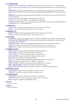
Contents
Getting Started
.........................................
2
Master window
.........................................
9
Overview window
...................................
12
Selected Channel window
.......................
25
Library window
.......................................
45
Premium Rack Library window
...............
48
Patch Editor window
...............................
49
Virtual Rack window
................................
53
Meter window
.........................................
67
Group/Link window
................................
69
Scene window
.........................................
73
Custom Fader Bank Setup window
.........
80
Custom Fader Bank window
...................
81
User Defined Keys Setup window
...........
82
User Defined Knobs Setup window
........
83
Sends On Fader window
.........................
85
Outport Setup window
...........................
86
Keyboard Shortcuts
.................................
88
Index
........................................................
89
*
Specifications and descriptions in this owner’s manual are
for information purposes only. Yamaha Corp. reserves the
right to change or modify products or specifications at any
time without prior notice.
CL Editor
CL Editor
CL Editor
Owner’s Manual
Owner’s Manual
Owner’s Manual
Description of menus and buttons
In the event that menu and button names on a Windows
system are different from those on a Mac, this manual uses
the Windows menu and button names followed by the Mac
menu and button names in parentheses.