Yamaha CL3 Cl Editor Owner's Manual - Page 14
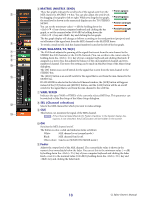
CPAN/ST/MC DSEL Channel selection ECUE FON GFader HChannel number IChannel name
 |
View all Yamaha CL3 manuals
Add to My Manuals
Save this manual to your list of manuals |
Page 14 highlights
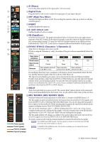
C PAN/ST/M(C) The PAN knob adjusts the panning of the signal that is sent from the INPUT CH to the STEREO bus L/R channels (or the L/C/R channels.) You can set this to the center value by C holding down the (< >) key of your computer keyboard and clicking this knob. The [ST] button is an on/off switch for the signal that is sent from the INPUT CH to the D E STEREO bus. The [M(C)] button is an on/off switch for the signal that is sent from the INPUT CH to the MONO bus. F If LCR MODE is selected in the Selected Channel window, the [LCR] button will appear instead of the [ST] button and [M(C)] button, and the [LCR] button will be an on/off switch for the signal that is sent from the INPUT CH to the LCR bus. G D SEL (Channel selection) Selects the INPUT CH for which you want to perform operations. E CUE This button cue-monitors the signal of the INPUT CH. NOTE If the Channel Select/Sends On Fader checkbox in the System Setup dialog box is not checked, the [CUE] button will be hidden in the screen. H F ON Switches the INPUT CH or send on/off. The button is color-coded and indicates status as follows: I White: INPUT CH is on (normal mode.) Black: INPUT CH/Send are off. Other colors: Send is on (SENDS ON FADER mode.) G Fader Adjusts the input level of the INPUT CH, or the send level. The fader is color-coded and indicates status as follows: White: You can adjust the input level of the INPUT CH (normal mode.) Gray: INPUT CH is off. Other colors: You can adjust the send level (SENDS ON FADER mode.) The current fader value is shown in the numerical box located immediately below the fader. You can set this to the minimum value (-∞ dB) by holding down the (< >) key of your computer keyboard and clicking the fader knob, or set it to the nominal value (0.00 dB) by holding down the (< >) key and key and clicking the fader knob. The numbers and alphabetical letters at the right of the fader indicate the DCA group and mute groups to which that channel belongs, and show the Recall Safe and Mute Safe status of the channel. Mute Group indicator DCA Group indicator Level Meter The numbers of mute groups to which this channel belongs are shown in red when those groups are muted. If the dimmer levels for those groups are set in a non-default status, those are shown in orange. The numbers of DCA groups to which this channel belongs are shown in yellow. This level meter is displayed at the same metering point with the input channel in Meter window setup (➥ p.67.) If this channel is set to Mute Safe, the M character is shown in green. If this channel is set to Recall Safe, the R character is shown in green. NOTE Click the indicator area to switch between 3 indicators. H Channel number This is the number of the INPUT CH. You can open the Selected Channel window for this channel by double-clicking this number. If you hold down the (< >) key of your computer keyboard and double-click this, the Selected Channel window will open as an additional view. I Channel name This is a text box that displays the channel name. You can also edit the channel name in this text box. 14 CL Editor Owner's Manual
-
 1
1 -
2
-
3
-
4
-
5
-
6
-
7
-
8
-
 9
9 -
 10
10 -
 11
11 -
 12
12 -
 13
13 -
 14
14 -
 15
15 -
 16
16 -
 17
17 -
 18
18 -
 19
19 -
20
-
21
-
22
-
23
-
24
-
25
-
26
-
27
-
28
-
29
-
30
-
31
-
32
-
33
-
34
-
35
-
36
-
37
-
38
-
39
-
40
-
41
-
42
-
43
-
44
-
45
-
46
-
47
-
48
-
49
-
50
-
51
-
52
-
53
-
54
-
55
-
56
-
57
-
58
-
59
-
60
-
61
-
62
-
63
-
64
-
65
-
66
-
67
-
68
-
69
-
70
-
71
-
72
-
73
-
74
-
75
-
76
-
77
-
78
-
79
-
80
-
81
-
82
-
83
-
84
-
85
-
86
-
87
-
88
-
89
 |
 |
