Yamaha CL3 Cl Editor Owner's Manual - Page 13
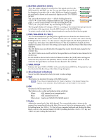
Ø Phase, Digital Gain, HPF High Pass Filter, INSERT, D. OUT Direct out, EQ Equalizer
 |
View all Yamaha CL3 manuals
Add to My Manuals
Save this manual to your list of manuals |
Page 13 highlights
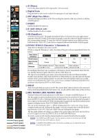
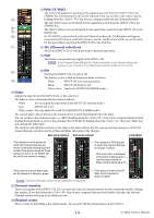
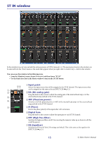
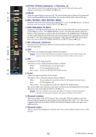
4 Ø (Phase) Inverts the phase polarity of the signal after AD conversion. 4 5 Digital Gain Drag the knob in the screen to adjust the input gain of each input channel. 5 6 HPF (High Pass Filter) Switches the high pass filter on/off. You can drag the numeric value up or down to edit the 6 cutoff frequency. 7 INSERT 7 Enables/disables the insert-in. 8 8 D. OUT (Direct out) 9 Enables/disables the direct output. 9 EQ (Equalizer) Switches the EQ on/off. The graph immediately below the button shows the approximate response of the EQ. Double-click within the graph to open the Selected Channel window of 0 the corresponding channel. To open the Selected Channel window as an additional view, hold down the (< >) key of your computer keyboard and double-click the graph. 0 DYNA1/DYNA2 (Dynamics 1/Dynamics 2) A Turns the two dynamics processors on/off. If Gate is assigned (Dynamics 1 only), the status of the gate is shown immediately below the B button. Gate status indication On/off status Open/closed status On Closed On Open On Off Open - Remarks Gain reduction amount Gain reduction Gain reduction is 30 dB or more amount is 0-30 dB amount is 0 dB - If something other than Gate is assigned, a GR meter is shown immediately below the button, and the amount of gain reduction is shown while this is on. The type for each dynamics processor can be selected in the Selected Channel window. Double-click anywhere other than the DYN1 or DYN2 button to open the Selected Channel window of the corresponding channel. To open the Selected Channel window as an additional view, hold down the (< >) key of your computer keyboard and double-click anywhere other than the DYN1 or DYN2 button. A DELAY Turns the input delay processors on/off. The current delay value is shown in the numerical box located immediately below the button. You can also edit the delay value in this text box. B MIX/MATRIX (MIX/MATRIX SEND) Switches between the send indications to MIX buses 1-24 and to MATRIX buses 1-8. The bar graphs located immediately below the button show the send level of the signals sent from the INPUT CH to VARI type MIX/MATRIX buses. You can also drag the bar graph to left or right to set the send level. While you drag the bar graph, the send level is shown in the numerical display area for PAN/TO STEREO MONO (C). You can set the minimum value (-∞ dB) by holding down the (< >) key of your computer keyboard and clicking the bar graph, or set the nominal value (0.00 dB) by holding down the (< >) key and key and clicking the bar graph. The bar graph display will change according to the send position (pre/post) and on/off status of the signal sent from the INPUT CH to the MIX/MATRIX buses. Pre/on (green) To switch a send on/off, click the channel number located at the left of the bar graph. NOTE For FIXED-type MIX buses, the bar graph is fixed at nominal level (0 dB), and only the on/off status is shown. Pre/off (green) Post/on (orange) NOTE In SENDS ON FADER mode, this button enables you to adjust the send level using the fader. Post/off (orange) 13 CL Editor Owner's Manual
-
 1
1 -
2
-
3
-
4
-
5
-
6
-
7
-
 8
8 -
 9
9 -
 10
10 -
 11
11 -
 12
12 -
 13
13 -
 14
14 -
 15
15 -
 16
16 -
 17
17 -
 18
18 -
19
-
20
-
21
-
22
-
23
-
24
-
25
-
26
-
27
-
28
-
29
-
30
-
31
-
32
-
33
-
34
-
35
-
36
-
37
-
38
-
39
-
40
-
41
-
42
-
43
-
44
-
45
-
46
-
47
-
48
-
49
-
50
-
51
-
52
-
53
-
54
-
55
-
56
-
57
-
58
-
59
-
60
-
61
-
62
-
63
-
64
-
65
-
66
-
67
-
68
-
69
-
70
-
71
-
72
-
73
-
74
-
75
-
76
-
77
-
78
-
79
-
80
-
81
-
82
-
83
-
84
-
85
-
86
-
87
-
88
-
89
 |
 |
