Yamaha CP2000 Owner's Manual - Page 10
Bridge Mode Hookup, BRIDGE Notes
 |
View all Yamaha CP2000 manuals
Add to My Manuals
Save this manual to your list of manuals |
Page 10 highlights
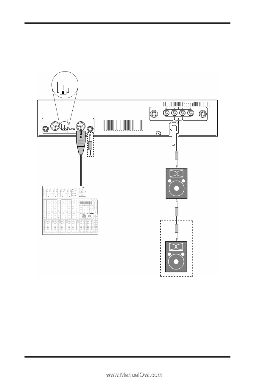
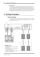
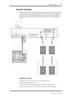
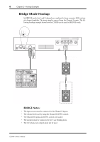
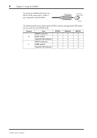
6 Chapter 2-Hookup Examples Bridge Mode Hookup In BRIDGE mode, the L and R channels are combined to form a massive 2000 watt single-channel amplifier. The input signal is sourced from the Channel L inputs. The following hookup example shows how the CP2000 can be used in BRIDGE mode. STEREO BRIDGE PARALLEL CHANNEL R 2 1 3 INPUT STEREO BRIDGE PARALLEL OFF ON CHANNEL L (BRIDGE) NEUTRIK 2 1 3 YAMAHA SPEAKER PROCESSING 2 1 1 2 CHANNEL R (-) BRIDGE (+) SPEAKERS CHANNEL L Total impedance: 4Ω min (2000 W) 8Ω (1300 W) MONO OUT Mixer BRIDGE Notes: • The input source must be connected to the Channel L inputs. • The volume level is set by using the Channel L LEVEL control. • The Channel R inputs and LEVEL control are inactive. • The speakers must be connected to the 5-way binding posts. • The 1/4" phone jack outputs must not be used. CP2000-Owner's Manual
-
 1
1 -
2
-
3
-
4
-
 5
5 -
 6
6 -
 7
7 -
 8
8 -
 9
9 -
 10
10 -
 11
11 -
 12
12 -
 13
13 -
 14
14 -
 15
15 -
16
-
17
-
18
-
19
-
20
 |
 |