Yamaha CP2000 Owner's Manual - Page 7
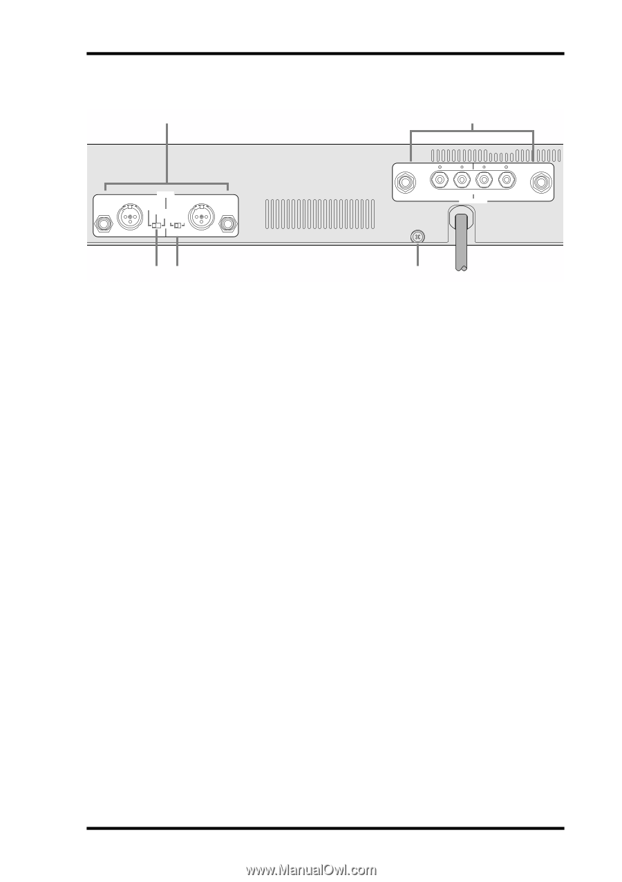
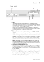
Rear Panel, AINPUTs BMode switch CYAMAHA SPEAKER PROCESSING switch DSPEAKERS connectors
 |
View all Yamaha CP2000 manuals
Add to My Manuals
Save this manual to your list of manuals |
Page 7 highlights
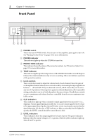
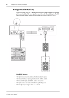
Rear Panel 1 Rear Panel 3 4 CHANNEL R 2 1 3 INPUT STEREO BRIDGE PARALLEL OFF ON CHANNEL L (BRIDGE) NEUTRIK 2 1 3 YAMAHA SPEAKER PROCESSING 23 2 1 1 2 CHANNEL R (-) BRIDGE (+) SPEAKERS CHANNEL L 5 A INPUTs The inputs for each CP2000 channel comprise of one 1/4" phone jack and one XLR-3-31-type connector. Both connectors are electronically balanced, although they can also be used with unbalanced sources. See "Connecting Inputs" on page 7 for more information. See also "Hookup Examples" on page 4. Since the phone jack and XLR-type connector on each channel are internally connected, either connector can be used to distribute the input signal to another amplifier. See "Daisy Chaining Inputs" on page 12 for more information. B Mode switch This switch is used to select the amplifier's mode of operation: STEREO, PARALLEL, or BRIDGE. STEREO-In this mode, which is typically used to amplify stereo sources, the L and R channels operate independently. PARALLEL-In this mode, the L and R channels operate independently but the input signal for both channels is sourced from the Channel L inputs. This mode is typically used with a mono source and allows independent volume control of two sets of speakers. BRIDGE-In this mode, the L and R channels are combined to form a massive 2000 watt single-channel amplifier. The input signal is sourced from the Channel L inputs, the volume level is set by using the Channel L LEVEL control, and the speakers are connected to the binding posts labelled BRIDGE. C YAMAHA SPEAKER PROCESSING switch This switch is used to activate the special EQ processing that optimizes the CP2000 for use with the Yamaha S115 and S112 loudspeakers. When other speakers are used, this switch should be set to OFF. See "Connecting S115 and S112 loudspeakers" on page 11 for more information. D SPEAKERS connectors The outputs for each CP2000 channel comprise of one 1/4" phone jack and one pair of 5-way binding posts. The 1/4" phone jacks accept 1/4" phone plugs, while the 5-way binding posts offer several methods of connection, including single or double banana plugs, spade lugs, or bare wires. See "Connecting Speakers" on page 9 for more information. See also "Hookup Examples" on page 4. CP2000-Owner's Manual
-
 1
1 -
 2
2 -
 3
3 -
 4
4 -
 5
5 -
 6
6 -
 7
7 -
 8
8 -
 9
9 -
 10
10 -
 11
11 -
 12
12 -
13
-
14
-
15
-
16
-
17
-
18
-
19
-
20
 |
 |