Yamaha CP2000 Owner's Manual - Page 13
Connecting Speakers, Caution for Speaker Connection, European Specifications Only - power
 |
View all Yamaha CP2000 manuals
Add to My Manuals
Save this manual to your list of manuals |
Page 13 highlights
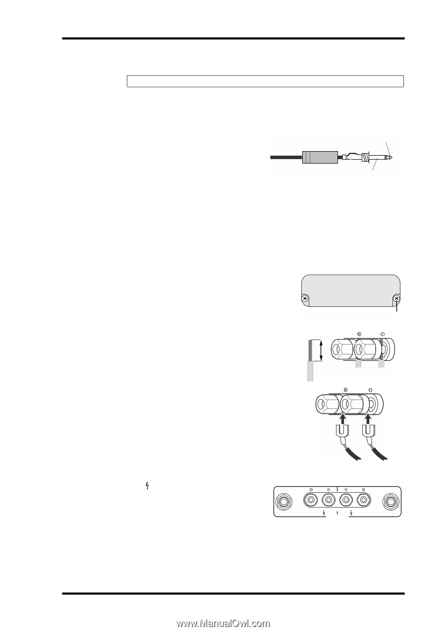
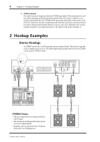
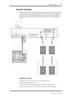
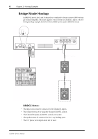
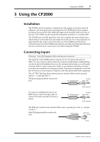
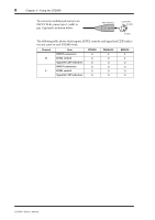
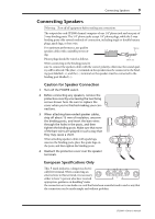
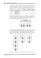
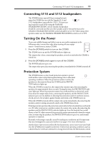
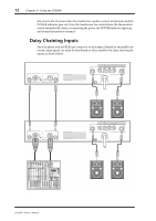
Connecting Speakers 9 Connecting Speakers Warning: Turn off all equipment before making any connections. The outputs for each CP2000 channel comprise of one 1/4" phone jack and one pair of 5-way binding posts. The 1/4" phone jacks accept 1/4" phone plugs, while the 5-way binding posts offer several methods of connection, including single or double banana plugs, spade lugs, or bare wire. For optimum performance, use quality Tip (+) speaker cables with a suitable power rat- 1/4" phone plug ing. Phone plugs should be wired as follows. Sleeve (-) When connecting to the binding posts, be sure to connect the speaker cables with the correct polarity, otherwise, the sound qual- ity will be affected. The plus (+) terminal on the speaker must be connected to the bind- ing post labelled (+), and the (-) terminal on the speaker must be connected to the binding post labelled (-). Caution for Speaker Connection 1 Turn off the POWER switch. 2 Before connecting any speakers, remove the protective cover by unscrewing the two fixing screws shown here. Be sure to replace the cover when you've finished making your connections. 3 When attaching bare-ended speaker cables, strip off about 15 mm of insulation, unscrew the binding posts, and insert the bare wires through the holes in the posts, and then tighten the binding posts. Make sure that none of the bare wires are splayed in such a way that they may cause a short. When attaching speaker cables with spade lugs, unscrew the binding posts, place the spade lugs on the posts, and then tighten the binding posts. 4 Reattach the protective cover over the speaker terminals. 15mm Screw 1 1 European Specifications Only This mark indicates a dangerous electri- 2 1 1 2 cally live terminal. When connecting an external wire to this terminal, it is necessary either to have "a person who have received CHANNEL R (-) BRIDGE (+) SPEAKERS CHANNEL L appropriate guidance on handling" make the connection or to use leads or a cord that have been manufactured in such a way that the connection can be made simply and without problem. CP2000-Owner's Manual
-
 1
1 -
2
-
3
-
4
-
5
-
6
-
7
-
 8
8 -
 9
9 -
 10
10 -
 11
11 -
 12
12 -
 13
13 -
 14
14 -
 15
15 -
 16
16 -
 17
17 -
 18
18 -
19
-
20
 |
 |