Yamaha CP2000 Owner's Manual - Page 18
Appendix, Specifications, Speci, cations - response
 |
View all Yamaha CP2000 manuals
Add to My Manuals
Save this manual to your list of manuals |
Page 18 highlights
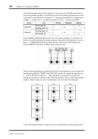
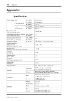
14 Appendix Appendix Specifications Power Output Level 8Ω/STEREO 1 kHz, THD+N=1% 4Ω/STEREO 8Ω/BRIDGE 1 kHz 20 ms, non-clip 2Ω/STEREO 4Ω/BRIDGE Power Bandwidth THD+N=0.2% (half power) Total Harmonic Distortion (THD+N) 4-8Ω/STEREO 20 Hz-20 kHz (half power) 8Ω/BRIDGE Intermodulation Distortion 60 Hz:7 kHz, 4:1, half power 4-8Ω/STEREO 8Ω/BRIDGE Frequency Response 8Ω, Po=1W Channel separation Half power, RL=8Ω LEVEL=max., input 600Ω shunt Residual Noise LEVEL=min., 12.7 kHz LPF, IHF-A network S/N Ratio 12.7 kHz LPF Damping Factor RL=8Ω, 1 kHz Sensitivity LEVEL=max., rated power into 8Ω Voltage Gain LEVEL=max. Input Impedance Controls Front panel Rear panel Connectors Indicators Input Output POWER PROTECTION TEMP CLIP SIGNAL 450 W + 450 W 650 W + 650 W 1300 W 1000 W + 1000 W 2000 W 10 Hz-40 kHz 0.1% 0.1% 0 dB, +0.5 dB, -1 dB f=20 Hz-50 kHz ≥70 dB, 1 kHz ≤ -70 dB 104 dB ≥200 +4 dB 33.8 dB 30 kΩ (balanced), 15 kΩ (unbalanced) POWER switch (push on/push off) LEVEL attenuator (31 position) x2 Mode switch (STEREO/BRIDGE/PARALLEL) YAMAHA SPEAKER PROCESSING switch (ON/OFF) XLR-3-31 type (balanced) L+R 1/4" phone jack (balanced) L+R 1/4" phone jack L+R 5-way binding post x1 x1 (green) x1 (red) x1 (red) heatsink temp ≥85°C x2 (red) x2 (green) output voltage ≥2 V x2 (yellow) output voltage ≥20 V CP2000-Owner's Manual
-
 1
1 -
2
-
3
-
4
-
5
-
6
-
7
-
8
-
9
-
10
-
11
-
12
-
 13
13 -
 14
14 -
 15
15 -
 16
16 -
 17
17 -
 18
18 -
 19
19 -
 20
20
 |
 |
