Yamaha CVP-900 Owner's Manual - Page 161
Keyboard Stand Assembly
 |
View all Yamaha CVP-900 manuals
Add to My Manuals
Save this manual to your list of manuals |
Page 161 highlights
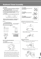
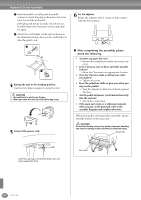
Keyboard Stand Assembly CAUTION ■ Be careful not to confuse parts, and be sure to install all parts in the correct orientation. Please assemble in accordance with the sequence given below. ■ Assembly should be carried out by at least two persons. ■ Be sure to use the correct screw size, as indicated below. Use of incorrect screws can damage the stand. ■ Be sure to tighten all screws upon completing the assembly of each unit. ■ To disassemble, reverse the assembly sequence given below. Have a Phillips-head (+) screwdriver ready. 1 Remove all parts from the box. Confirm that all parts shown in the illustration are included. Main unit Lean the unit against the wall as shown below. Legs Pedal box CAUTION Do not place the main unit with the rear side facing down. CAUTION Do not lay the main unit upside down on the floor. CAUTION Do not position the main unit so that its bottom is in contact with floor. 2 Attach two front legs and a rear leg. Refer to the diagram below to verify the orientation of the legs. Rear leg Front leg Front leg AC power cord 6×25 mm fixing screws ×16 Install and tighten four screws on each leg, starting with one of the front legs. Cord holder How to position the main unit CAUTION Be careful not to pinch your fingers. 3 Install the pedal box. 1 Remove the plastic tie that affixes the pedal cord to the upper portion of the pedal box. Be sure to position the keyboard side on the bottom. Spread a large soft cloth, such as a blanket, on the floor. Place the unit on the cloth with the key cover closed and the keyboard side on the bottom and lean the unit against the wall so that the unit will not fall or slip. Place a soft cloth against the wall to protect the instrument and the wall from scratches. Plastic tie 2 Align the cord with the groove on the unit, and attach the pedal box using four screws. CVP-900 161
-
 1
1 -
2
-
3
-
4
-
5
-
6
-
7
-
8
-
9
-
10
-
11
-
12
-
13
-
14
-
15
-
16
-
17
-
18
-
19
-
20
-
21
-
22
-
23
-
24
-
25
-
26
-
27
-
28
-
29
-
30
-
31
-
32
-
33
-
34
-
35
-
36
-
37
-
38
-
39
-
40
-
41
-
42
-
43
-
44
-
45
-
46
-
47
-
48
-
49
-
50
-
51
-
52
-
53
-
54
-
55
-
56
-
57
-
58
-
59
-
60
-
61
-
62
-
63
-
64
-
65
-
66
-
67
-
68
-
69
-
70
-
71
-
72
-
73
-
74
-
75
-
76
-
77
-
78
-
79
-
80
-
81
-
82
-
83
-
84
-
85
-
86
-
87
-
88
-
89
-
90
-
91
-
92
-
93
-
94
-
95
-
96
-
97
-
98
-
99
-
100
-
101
-
102
-
103
-
104
-
105
-
106
-
107
-
108
-
109
-
110
-
111
-
112
-
113
-
114
-
115
-
116
-
117
-
118
-
119
-
120
-
121
-
122
-
123
-
124
-
125
-
126
-
127
-
128
-
129
-
130
-
131
-
132
-
133
-
134
-
135
-
136
-
137
-
138
-
139
-
140
-
141
-
142
-
143
-
144
-
145
-
146
-
147
-
148
-
149
-
150
-
151
-
152
-
153
-
154
-
155
-
 156
156 -
 157
157 -
 158
158 -
 159
159 -
 160
160 -
 161
161 -
 162
162 -
 163
163 -
 164
164 -
 165
165 -
 166
166 -
167
-
168
-
169
-
170
-
171
-
172
-
173
-
174
-
175
-
176
 |
 |
