Yamaha EMX5016CF Owner's Manual - Page 25
Feedback Suppressor, MAXIMIZE ON switch, LIMITER Indicators, Maximum Output Switch, POWER AMP Switch - 8 ohm
 |
UPC - 086792856216
View all Yamaha EMX5016CF manuals
Add to My Manuals
Save this manual to your list of manuals |
Page 25 highlights
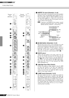
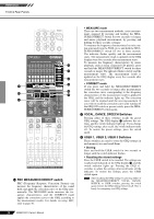
Reference Front & Rear Panels [ Feedback Suppressor This function monitors the stereo-bus signal for howling and creates notch filters (filters which cut specific frequencies) to eliminate the howling. There are two methods: AUTO mode monitors the signal periodically, and MANUAL mode searches for each feedback point individually. You can use both methods in tandem or either method alone. • AUTO mode Pressing the AUTO ON switch turns on the indicator and monitors for howling periodically. If howling is found, the corresponding notch filter is created automatically. Pressing the AUTO ON switch again turns off Feedback Suppressor (notch filters) and the switch indicator. To clear the notch filters, press and hold the AUTO ON switch for two seconds or longer. The indicator flashes when all notch filters are cleared. As long as you do not clear the notch filters, the filter settings will be retained even when you turn off the mixer's power. NOTE A notch filter created by AUTO mode will be reduced by 3 dB a minute after the filter has been created. • MANUAL mode Press the MANUAL DETECT switch to check for the next feedback point in the signal. If howling is found, (up to) one notch filter is created automatically. During the check, the MANUAL DETECT switch indicator flashes. The check is stopped when howling is found or not found for five seconds. If notch filters are already created and another howling point is not found, the indicator goes off for a second, then lights up again. MANUAL mode detects howling more sensitively than AUTO mode. Use of this mode may mistakenly identify musical notes as howling during a performance; however, this mode is handy to set up precautionary notch filters beforehand by intentionally raising the levels and finding the howling points. NOTE • If a notch filter is created by pressing the MANUAL DETECT switch, the MANUAL ON switch is turned on automatically. To turn off Feedback Suppressor, press the MANUAL ON switch. The switch indicator turns off. • If no notch filters are created, pressing the MANUAL ON switch cannot turn on Feedback Suppressor. To clear the notch filters, press and hold the MANUAL ON switch for two seconds or longer. The indicator flashes when all notch filters are cleared. As long as you do not clear the notch filters, the filter settings will be retained even when you turn off the mixer's power. \ MAXIMIZE ON switch When this switch is turned on, a multi-band (3-band) compressor is applied to the Stereo L/R bus signal enhancing the sound and volume of the overall output. Turning on the switch lights up the indicator. NOTE Turning on the power while holding the GEQ ON switch W and MAXIMIZE ON switch \ restores the initial factory settings for GEQ, Effects, Feedback Suppressor, and MAXIMIZE. ] LIMITER Indicators The lamp lights up when the amplified signal output at the SPEAKERS jacks hits its maximum value. CAUTION The lamp indicates that the limiter has come on. If the lamps are flashing frequently, the load on the amp is too high and there is risk of damage to your equipment. Reduce the setting of the ST master fader l or the AUX1 or AUX2 fader f until the lamps flash only briefly or not at all. ^ Maximum Output Switch This selector lets you set the maximum output from for the 2-channel internal amp to any of three levels. Set this to match the size of your room or the input capacity of your speakers. 500W: Maximum 500W + 500W/4 ohms. 200W: Maximum 200W + 200W/4 ohms. 75W: Maximum 75W + 75W/4 ohms a POWER AMP Switch Selects the output that gets sent to the SPEAKERS jacks, as follows. L/R: SPEAKERS jacks A1 and A2 output the signal from the Stereo L bus, while jacks B1 and B2 output the signal from the Stereo R bus. The overall volume is adjusted by the ST master fader. AUX1/MONO: SPEAKERS jacks A1 and A2 output the signal from the AUX 1 bus; the volume for this signal can be adjusted using the AUX1 fader. SPEAKERS jacks B1 and B2 output the mix of the signals on the Stereo L and R buses; the volume can be adjusted with the ST master fader. AUX1/AUX2: SPEAKERS jacks A1 and A2 output the signal from the AUX 1 bus, while jacks B1 and B2 output the signal from the AUX2 bus. Volumes can be adjusted using the AUX1 and AUX2 faders, respectively. b YS Processing Switch This switch turns Yamaha Speaker Processing on or off. The processor adjusts the speaker's bass ranges so as to compensate, for example, for a lack of subwoofers. Note however that the resulting frequency balance may vary according to the speakers you are using. EMX5016CF Owner's Manual 25
-
 1
1 -
2
-
3
-
4
-
5
-
6
-
7
-
8
-
9
-
10
-
11
-
12
-
13
-
14
-
15
-
16
-
17
-
18
-
19
-
 20
20 -
 21
21 -
 22
22 -
 23
23 -
 24
24 -
 25
25 -
 26
26 -
 27
27 -
 28
28 -
 29
29 -
 30
30 -
31
-
32
-
33
-
34
-
35
-
36
-
37
-
38
-
39
-
40
 |
 |
