Yamaha EXo8 EXi8/EXo8 Owners Manual - Page 10
Setup
 |
View all Yamaha EXo8 manuals
Add to My Manuals
Save this manual to your list of manuals |
Page 10 highlights
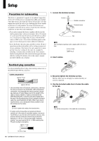
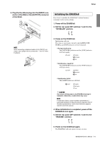
Setup Precautions for rackmounting This device is guaranteed to operate at an ambient temperature of 0 to 40 °C. If this device is mounted in an EIA rack together with other devices, heat from the various devices may cause the temperature inside the rack to rise, rendering this device unable to perform to its full potential. To ensure that heat does not accumulate inside this device, please ensure that the following conditions are met when rack-mounting it. • If you plan to mount this device together with devices that tend to generate heat, such as power amps, allow 1U or more of vacant space between this device and other devices. (However, you do not need larger than 1U space with the MTX series or XMV series.) Also attach ventilation panels in this space or leave them open to ensure sufficient ventilation. • Leave the back of the rack open, and allow at least 10 cm of space between the rack and the wall or ceiling to ensure sufficient ventilation. If the back of the rack cannot be left open, provide forced air cooling for the rack, for example by installing a commercially available fan kit. If you install a fan kit, leaving the back of the rack closed may provide more effective cooling. For details, refer to the owner's manual provided with the rack or fan kit. Euroblock plug connection Use the included Euroblock plugs when making connections to the [INPUT]/[OUTPUT] connectors. Cable preparation approx. 7 mm approx. 20 mm • Use stranded wire for Euroblock connections, and strip the wire as shown in the illustration. With a Euroblock connection, the stranded wire may be prone to breakage because of metal fatigue due to the weight of the cable or due to vibration. Cables connected to the [INPUT]/[OUTPUT] connectors should be fastened to the tab of the Euroblock plug (3-pin) using the included cable ties (see illustration at right). When rack-mounting the device, use a lacing bar when possible to bundle and secure the cable. NOTE Do not tin (plate with solder) the stranded wire. • If cables will be frequently connected and disconnected, as in the case of a portable system, we recommend that you use ferrules with insulation sleeves. Use a ferrule whose conductor portion has an external diameter of 1.6 mm or less and a length of approximately 7 mm such as the AI 0,5 - 6 WH made by the Phoenix Contact corporation. approx. 7 mm 1. Loosen the terminal screws. Loosen Slotted screwdriver Terminal screw Euroblock plug Tab NOTE Use a slotted screwdriver with a blade width of 3 mm or less. 3 mm or less 2. Insert cables. +- G 3. Securely tighten the terminal screws. Pull the cables (not too strongly) to confirm that they are securely connected. 4. Use the included cable ties to fasten the cable to the tab. NOTE Trim off the extra portion of the cable tie as necessary. 1.6 mm or less 10 EXi8/EXo8 Owner's Manual
-
 1
1 -
2
-
3
-
4
-
 5
5 -
 6
6 -
 7
7 -
 8
8 -
 9
9 -
 10
10 -
 11
11 -
 12
12 -
 13
13 -
 14
14 -
 15
15 -
16
-
17
-
18
-
19
-
20
 |
 |
