Yamaha EXo8 EXi8/EXo8 Owners Manual - Page 7
Controls and Connectors
 |
View all Yamaha EXo8 manuals
Add to My Manuals
Save this manual to your list of manuals |
Page 7 highlights
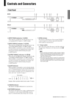
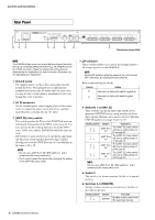
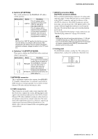
Controls and Connectors Front Panel EXi8 qw r t yu i EXo8 e r t yu i q [INPUT PEAK] indicators 1-8 (EXi8) These indicators will light red when the input level of the corresponding INPUT channel is -3 dBFS or higher. w [INPUT SIGNAL] indicators 1-8 (EXi8) These indicators will light green when the input level of the corresponding INPUT channel is -40 dBFS or higher. When a problem or abnormality occurs in the unit, the indicator that corresponds to the appropriate alert number will flash in green together with the flashing front panel [ALERT] indicator. e [OUTPUT SIGNAL] indicators 1-8 (EXo8) These indicators will light green when the output level of the corresponding OUTPUT channel is -40 dBFS or higher. When a problem or abnormality occurs in the unit, the indicator that corresponds to the appropriate alert number will flash in green together with the flashing front panel [ALERT] indicator. r [ALERT] indicator When a problem or abnormality occurs in the unit, this indicator will flash in red and at the same time the [INPUT SIGNAL] or [OUTPUT SIGNAL] indicator that corresponds to the alert number will flash in green. For explanations of the alerts, refer to the "Alert list" on page 13. Alert number u [YDIF] indicator This indicator will light green if the rear panel [YDIF IN] connector (page 9) is correctly connected to the [YDIF OUT] connector of another device. i Power switch This is the power switch. The power is on if the switch is in the position. The power is off if the switch is in the position. NOTE • Do not cycle the power switch in rapid succession. Wait at least 6 seconds before turning the power switch on after it has been turned off. Failing to observe this precaution may cause malfunctions. • Even when the power switch is turned off, a small amount of current is flowing through the unit. If you plan not to use the unit for a long period of time, remove the power cable from the AC outlet. Example: When a problem related to alert number "3" occurs t [POWER] indicator This indicator will light when this device is powered-on. y [NETWORK] indicator This indicator will light green if a link is established with an external device via the rear panel NETWORK connector (page 9). It will flash while data is being sent or received. EXi8/EXo8 Owner's Manual 7
-
 1
1 -
 2
2 -
 3
3 -
 4
4 -
 5
5 -
 6
6 -
 7
7 -
 8
8 -
 9
9 -
 10
10 -
 11
11 -
 12
12 -
13
-
14
-
15
-
16
-
17
-
18
-
19
-
20
 |
 |
