Yamaha EXo8 EXi8/EXo8 Owners Manual - Page 9
Switch 6 IP SETTING, Switches 7-8 START UP MODE, NETWORK connector, YDIF] connectors, INPUT]
 |
View all Yamaha EXo8 manuals
Add to My Manuals
Save this manual to your list of manuals |
Page 9 highlights
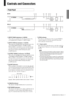
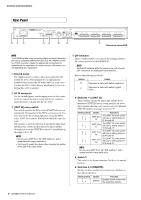
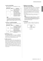
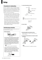
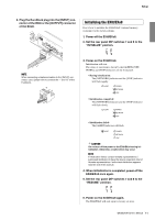
Controls and Connectors Switch 6 (IP SETTING) This switch specifies how the EXi8/EXo8's IP address will be specified. Switch position Option UNIT ID PC Functions The IP address will be specified according to the UNIT ID, and will be 192.168.0.(UNIT ID). The IP address will be determined by the settings of the system's application software. (See the user's manual of the corresponding application software.) NOTE Set this to the "UNIT ID" position the first time you connect this device to a computer after purchase. After specifying the IP address from the system's dedicated application software, change this switch to the "PC" position. Switches 7-8 (START UP MODE) These specify whether the EXi8/EXo8 will be initialized when it is powered-on. Switch position Option Functions RESUME This is the normal operating mode. When you power-on the EXi8/EXo8, it will start up in the same state in which it was when the power was turned off. Initializes the EXi8/EXo8, INITIALIZE returning it to the factory-set state (page 11). t NETWORK connector This is an Ethernet connector that supports AutoMDI/MDIX. It enables communication via a network switch with an MTX network or external controller. Use a CAT5e or better Ethernet STP cable (shielded twisted pair cable). y [YDIF] connectors These connectors are used to make a ring connection with the devices that comprise the system, allowing digital audio signals to be transmitted and received. Use CAT5e or better Ethernet STP cables (shielded twisted pair cables) that have all eight pins connected in a straight connection. The maximum cable length between devices is 30 meters, and you can connect up to total seven EXi8 and EXo8 devices. For details, refer to the user's manual of the corresponding application software. u [INPUT] connectors (EXi8) [OUTPUT] connectors (EXo8) These are balanced input/output connectors for analog audio input and output. Connect line level devices or microphones to the [INPUT] connectors, and line level devices to the [OUTPUT] connectors. The [INPUT] connectors provide head amps, and can also provide +48V phantom power. The system's dedicated application software is used to specify the gain of the internal head amps and to turn the phantom power on/off. Use the included Euroblock plugs to make connections (see "Euroblock plug connection" on page 10 for details). NOTE Adjusting the internal head amp gain between +17 dB and +18 dB will internally turn PAD on/off. Noise may occur if there is an impedance difference between the Hot and Cold of a device connected to the [INPUT] connectors while phantom power is being used. i Cooling vent The EXi8/EXo8 contains a cooling fan. The cooling air is exhausted here, so please be careful not to block this vent. Cooling vent EXi8/EXo8 Owner's Manual 9
-
 1
1 -
2
-
3
-
 4
4 -
 5
5 -
 6
6 -
 7
7 -
 8
8 -
 9
9 -
 10
10 -
 11
11 -
 12
12 -
 13
13 -
 14
14 -
15
-
16
-
17
-
18
-
19
-
20
 |
 |
