Yamaha EXo8 EXi8/EXo8 Owners Manual - Page 8
Rear Panel
 |
View all Yamaha EXo8 manuals
Add to My Manuals
Save this manual to your list of manuals |
Page 8 highlights
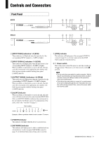
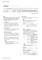
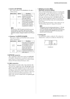
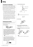
Controls and Connectors Rear Panel ON iq w er ty u * Illustration shows EXi8. NOTE The EXi8/EXo8 has some connectors that are shaped identically but have a completely different function (e.g., NETWORK connector, [YDIF] connector). Make the appropriate connections as instructed by the explanation for each connector. Otherwise, you risk damaging your equipment. q Ground screw The supplied power cord has a three-prong plug that will ground the device when plugged into an appropriately grounded three-prong type AC mains outlet. In some cases, you may be able to reduce hum or interference by also connecting this screw to ground. w AC IN connector Use the included power cord to supply power to this connector. First, connect the power cord to this device, and then insert the power cord plug into the AC outlet. e [UNIT ID] rotary switch This switch specifies the ID by which EXi8/EXo8 units are individually distinguished in the MTX system network. You must specify the ID avoiding duplicates among the MTX series, XMV series and the EXi8/EXo8 within the same network. DIP switches 1 and 2 described in r specify the upper digit, and this rotary switch specifies the lower digit, together allowing you to set the UNIT ID to one of 63 possibilities in the range of 01 to 3F. NOTE • Do not use a UNIT ID of "00" (DIP switches 1 and 2 upward and the rotary switch at 0). • You'll need to restart the device after changing the setting of the [UNIT ID] rotary switch. r DIP switches These switches enable you to specify the settings related to the startup operation of the EXi8/EXo8. NOTE Set the DIP switches while the power to the unit is turned OFF. Otherwise, the setting will not be effective. Refer to the following for details. Switch Status Represent a status with switch toggled up. Represent a status with switch toggled down. Switches 1-2 (UNIT ID) These switches specify the upper digit and the abovementioned [UNIT ID] rotary switch specifies the lower digit, together allowing you to specify one of 63 different UNIT ID numbers in a range from 01 to 3F. Switch position Option UNIT ID is "0x" UNIT ID is "1x" UNIT ID is "2x" UNIT ID is "3x" Functions The [UNIT ID] rotary switch will have a setting range of 01 through 0F. The [UNIT ID] rotary switch will have a setting range of 10 through 1F. The [UNIT ID] rotary switch will have a setting range of 20 through 2F. The [UNIT ID] rotary switch will have a setting range of 30 through 3F. NOTE Do not use a UNIT ID of "00" (DIP switches 1 and 2 upward and the rotary switch at 0). Switch 3 This switch is for future expansion. Set this to its upward position. Switches 4-5 (REMOTE) Settings of these switches are not necessary. Set these to their upward position. Switch position Option NATIVE Function Enables remote control with the supported devices. 8 EXi8/EXo8 Owner's Manual
-
 1
1 -
2
-
 3
3 -
 4
4 -
 5
5 -
 6
6 -
 7
7 -
 8
8 -
 9
9 -
 10
10 -
 11
11 -
 12
12 -
 13
13 -
14
-
15
-
16
-
17
-
18
-
19
-
20
 |
 |
