Yamaha LS9-32 Owner's Manual - Page 47
HA (head amp) settings, Making HA settings for one channel at
 |
View all Yamaha LS9-32 manuals
Add to My Manuals
Save this manual to your list of manuals |
Page 47 highlights
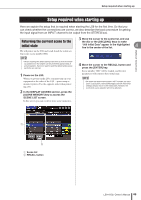
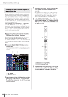
Setup required when starting up 3 Use the buttons in the window to select the clock source to which the LS9 will synchronize. ● If you want the clock source to be the clock data included in a digital audio signal from a slot Turn on a valid 2-channel button for the corresponding slot. ● If you want the clock source to be the clock data included in the digital audio signal from the 2TR IN DIGITAL jack Turn on the 2TR IN button. NOTE • If a conventional CD player or similar device is connected to the 2TR IN DIGITAL jack, use that device as the clock master. In some cases, noise may occur when synchronization is lost. ● If you want the word clock data from the WORD CLOCK IN jack to be the clock source Turn on the WC IN button. ● If you want the LS9's internal clock to be the clock source Turn on the INT48k (sampling frequency: 48 kHz) or INT44.1k (sampling frequency: 44.1 kHz) button. If the LS9 is correctly operating with the new clock, the symbol located immediately above the corresponding button will turn light blue. Also, the frequency of the selected clock source is shown in the upper left of the window. 4 To close the WORD CLOCK popup window, move the cursor to the CLOSE button (or the × symbol in the upper right of the window) and press the [ENTER] key. NOTE • The word clock setting is maintained even if you turn off the power. If you've set the LS9 to synchronize to the word clock of an external device, be aware that an error message will appear and the system will not operate correctly if the external device is powered-off when you power-cycle the LS9 or if the connection is disconnected. HA (head amp) settings Here we explain how to adjust the HA (head amp) gain, switch phantom power on/off, and switch the phase for each input channel to which you've connected a mic or instrument. When setting HA-related parameters on the LS9, you can either use the SELECTED CHANNEL section or the SELECTED CH VIEW screen in the display to make set- tings for a single channel at a time, or use the popup win- 4 dow to make settings for eight channels at a time. Connections and setup ● Making HA settings for one channel at a time Select the channel that you want to set, and use the SELECTED CHANNEL section or the SELECTED CH VIEW screen of the display to make HA settings. 1 Make sure that a mic or instrument is connected to the INPUT jack (→ p. 41). 2 Make sure that the fader layer that contains the desired channel is selected in the LAYER section. If necessary, use the keys of the LAYER section to switch fader layers. LS9-16 LS9-32 3 Press the [SEL] key of the channel for the INPUT jack you want to operate, so that the LED is lit. That channel is now selected for operations in the SELECTED CHANNEL section. 1 2 1 [SEL] key B Meter LEDs LS9-16/32 Owner's Manual 47
-
 1
1 -
2
-
3
-
4
-
5
-
6
-
7
-
8
-
9
-
10
-
11
-
12
-
13
-
14
-
15
-
16
-
17
-
18
-
19
-
20
-
21
-
22
-
23
-
24
-
25
-
26
-
27
-
28
-
29
-
30
-
31
-
32
-
33
-
34
-
35
-
36
-
37
-
38
-
39
-
40
-
41
-
 42
42 -
 43
43 -
 44
44 -
 45
45 -
 46
46 -
 47
47 -
 48
48 -
 49
49 -
 50
50 -
 51
51 -
 52
52 -
53
-
54
-
55
-
56
-
57
-
58
-
59
-
60
-
61
-
62
-
63
-
64
-
65
-
66
-
67
-
68
-
69
-
70
-
71
-
72
-
73
-
74
-
75
-
76
-
77
-
78
-
79
-
80
-
81
-
82
-
83
-
84
-
85
-
86
-
87
-
88
-
89
-
90
-
91
-
92
-
93
-
94
-
95
-
96
-
97
-
98
-
99
-
100
-
101
-
102
-
103
-
104
-
105
-
106
-
107
-
108
-
109
-
110
-
111
-
112
-
113
-
114
-
115
-
116
-
117
-
118
-
119
-
120
-
121
-
122
-
123
-
124
-
125
-
126
-
127
-
128
-
129
-
130
-
131
-
132
-
133
-
134
-
135
-
136
-
137
-
138
-
139
-
140
-
141
-
142
-
143
-
144
-
145
-
146
-
147
-
148
-
149
-
150
-
151
-
152
-
153
-
154
-
155
-
156
-
157
-
158
-
159
-
160
-
161
-
162
-
163
-
164
-
165
-
166
-
167
-
168
-
169
-
170
-
171
-
172
-
173
-
174
-
175
-
176
-
177
-
178
-
179
-
180
-
181
-
182
-
183
-
184
-
185
-
186
-
187
-
188
-
189
-
190
-
191
-
192
-
193
-
194
-
195
-
196
-
197
-
198
-
199
-
200
-
201
-
202
-
203
-
204
-
205
-
206
-
207
-
208
-
209
-
210
-
211
-
212
-
213
-
214
-
215
-
216
-
217
-
218
-
219
-
220
-
221
-
222
-
223
-
224
-
225
-
226
-
227
-
228
-
229
-
230
-
231
-
232
-
233
-
234
-
235
-
236
-
237
-
238
-
239
-
240
-
241
-
242
-
243
-
244
-
245
-
246
-
247
-
248
-
249
-
250
-
251
-
252
-
253
-
254
-
255
-
256
-
257
-
258
-
259
-
260
-
261
-
262
-
263
-
264
-
265
-
266
-
267
-
268
-
269
-
270
-
271
-
272
-
273
-
274
-
275
-
276
-
277
-
278
-
279
-
280
-
281
-
282
-
283
-
284
-
285
-
286
-
287
-
288
-
289
-
290
 |
 |
