Yamaha RX-V863 Owner's Manual - Page 25
Connecting other components, Connecting a DVD player
 |
View all Yamaha RX-V863 manuals
Add to My Manuals
Save this manual to your list of manuals |
Page 25 highlights
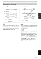
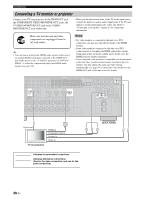
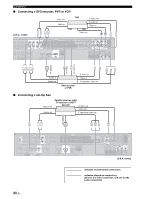
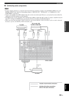
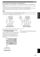
PREPARATION Connections Connecting other components Make sure that this unit and other components are unplugged from the AC wall outlets. Notes • When "VIDEO CONV." is set to "OFF" (see page 98), be sure to make the same type of video connections as those made for your TV (see page 20). For example, if you connected your TV to the VIDEO MONITOR OUT jack of this unit, connect your other components to the VIDEO jacks. ■ Connecting a DVD player • When "VIDEO CONV." is set to "ON" (see page 98), the converted video signals are output only at the MONITOR OUT jacks. To record a source, make the same type of video connections between each component. • To make a digital connection to a component other than the default component assigned to each DIGITAL INPUT or DIGITAL OUTPUT jack, select the corresponding setting for "OPTICAL OUT", "OPTICAL IN", or "COAXIAL IN" in "I/O ASSIGNMENT" (see page 95). • If you connect your DVD player to both the DIGITAL INPUT (OPTICAL) and the DIGITAL INPUT (COAXIAL) jacks, priority is given to the signals input at the DIGITAL INPUT (COAXIAL) jack. Optical out Coaxial out Audio out DVD player S-video out Video out Component video out HDMI out C LR PR PB Y VS O AUDIO L MULTI CH INPUT FRONT (8CH) CENTER PRE OUT SINGLE CENTER GND R PHONO IN MD/ OUT CD (PLAY) CD-R (REC) DVD DTV/CBL IN OUT DVR IN OUT VCR SUB SB (8CH) SURROUND WOOFER ZONE 2 HDMI OUT FRONT SURROUND SUR. BACK 1 2 SUBWOOFER SIRIUS MD/CD-R MD/CD-R DVD DTV/CBL CD DVD 1 2 3 4 5 6 DIGITAL XM OUTPUT OPTICAL DIGITAL INPUT COAXIAL FRONT B/ZONE B/ ZONE 2/PRESENCE R EXTRA SP L FRONT A R L FM 75Ω UNBAL. GND AM HD Radio ANTENNA REMOTE TRIGGER OUT +12V IN OUT 15mA MAX. DVD DTV/CBL IN1 IN2 SPEAKERS CENTER SURROUND R L DVR OUT IN3 SURROUND BACK/BI-AMP R L DOCK VIDEO VIDEO S VIDEO DVD DTV/CBL IN OUT DVR IN OUT VCR COMPONENT VIDEO PR A DVD PB Y PR B DTV/CBL PB MONITOR OUT Y MONITOR OUT AC OUTLETS SWITCHED 120V 80Hz 100W MAX. TOTAL 0.8A MAX. TOTAL C DVR (U.S.A. model) indicates recommended connections indicates alternative connections (One for the video connection, and one for the audio connection) English 21 En
-
 1
1 -
2
-
3
-
4
-
5
-
6
-
7
-
8
-
9
-
10
-
11
-
12
-
13
-
14
-
15
-
16
-
17
-
18
-
19
-
 20
20 -
 21
21 -
 22
22 -
 23
23 -
 24
24 -
 25
25 -
 26
26 -
 27
27 -
 28
28 -
 29
29 -
 30
30 -
31
-
32
-
33
-
34
-
35
-
36
-
37
-
38
-
39
-
40
-
41
-
42
-
43
-
44
-
45
-
46
-
47
-
48
-
49
-
50
-
51
-
52
-
53
-
54
-
55
-
56
-
57
-
58
-
59
-
60
-
61
-
62
-
63
-
64
-
65
-
66
-
67
-
68
-
69
-
70
-
71
-
72
-
73
-
74
-
75
-
76
-
77
-
78
-
79
-
80
-
81
-
82
-
83
-
84
-
85
-
86
-
87
-
88
-
89
-
90
-
91
-
92
-
93
-
94
-
95
-
96
-
97
-
98
-
99
-
100
-
101
-
102
-
103
-
104
-
105
-
106
-
107
-
108
-
109
-
110
-
111
-
112
-
113
-
114
-
115
-
116
-
117
-
118
-
119
-
120
-
121
-
122
-
123
-
124
-
125
-
126
-
127
-
128
-
129
-
130
-
131
-
132
-
133
-
134
-
135
-
136
-
137
-
138
-
139
-
140
-
141
-
142
-
143
-
144
-
145
-
146
-
147
-
148
-
149
-
150
-
151
-
152
 |
 |
