Yamaha RX-V863 Owner's Manual - Page 30
Using the VIDEO AUX jacks on the front panel, Using REMOTE IN/OUT jacks - remote control
 |
View all Yamaha RX-V863 manuals
Add to My Manuals
Save this manual to your list of manuals |
Page 30 highlights
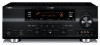
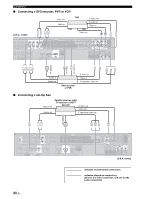
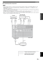
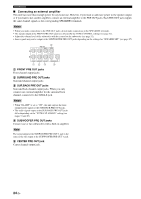
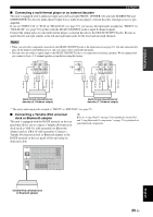
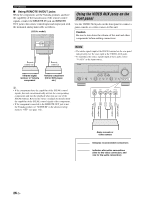
Connections ■ Using REMOTE IN/OUT jacks When the components are the Yamaha products and have the capability of the transmission of the remote control signals, connect the REMOTE IN jack and REMOTE OUT jack to the remote control input and output jack with the monaural analog mini cable as follows. (U.S.A. model) FM 75Ω UNBAL. GND AM HD Radio ANTENNA REMOTE TRIGGER OUT +12V IN OUT 15mA MAX. Remote control out Remote control in Infrared signal receiver or Yamaha component Yamaha component (CD or DVD player, etc.) Using the VIDEO AUX jacks on the front panel Use the VIDEO AUX jacks on the front panel to connect a game console or a video camera to this unit. Caution Be sure to turn down the volume of this unit and other components before making connections. Notes • The audio signals input at the DOCK terminal on the rear panel take priority over the ones input at the VIDEO AUX jacks. • To reproduce the source signals input at these jacks, select "V-AUX" as the input source. VOLUME SPEAKERS EDIT SEARCH MODE BAND CATEGORY A/B/C/D/E PRESET/TUNING/CH MEMORY INFO ZONE 2 ON/OFF ZONE CONTROL STANDBY /ON SYSTEM OFF PHONES SILENT CINEMA TONE CONTROL SCENE 1 2 3 4 PROGRAM STRAIGHT PURE DIRECT AUDIO SELECT INPUT EFFECT OPTIMIZER MIC VIDEO AUX S VIDEO VIDEO L AUDIO R OPTICAL y • If the components have the capability of the SCENE control signals, this unit can automatically activate the corresponding components and start the playback when you use one of the SCENE buttons. Refer to the owner's manuals for details about the capability of the SCENE control signals of the components. • If the component connected to the REMOTE OUT jack is not the Yamaha product, set "SCENE IR" in the advanced setup menu to "OFF" (see page 112). S VIDEO VIDEO L AUDIO R OPTICAL S V L R O Optical output Audio output Video output S-Video output Game console or video camera indicates recommended connections indicates alternative connections (One for the video connection, and one for the audio connection) 26 En
-
 1
1 -
2
-
3
-
4
-
5
-
6
-
7
-
8
-
9
-
10
-
11
-
12
-
13
-
14
-
15
-
16
-
17
-
18
-
19
-
20
-
21
-
22
-
23
-
24
-
 25
25 -
 26
26 -
 27
27 -
 28
28 -
 29
29 -
 30
30 -
 31
31 -
 32
32 -
 33
33 -
 34
34 -
 35
35 -
36
-
37
-
38
-
39
-
40
-
41
-
42
-
43
-
44
-
45
-
46
-
47
-
48
-
49
-
50
-
51
-
52
-
53
-
54
-
55
-
56
-
57
-
58
-
59
-
60
-
61
-
62
-
63
-
64
-
65
-
66
-
67
-
68
-
69
-
70
-
71
-
72
-
73
-
74
-
75
-
76
-
77
-
78
-
79
-
80
-
81
-
82
-
83
-
84
-
85
-
86
-
87
-
88
-
89
-
90
-
91
-
92
-
93
-
94
-
95
-
96
-
97
-
98
-
99
-
100
-
101
-
102
-
103
-
104
-
105
-
106
-
107
-
108
-
109
-
110
-
111
-
112
-
113
-
114
-
115
-
116
-
117
-
118
-
119
-
120
-
121
-
122
-
123
-
124
-
125
-
126
-
127
-
128
-
129
-
130
-
131
-
132
-
133
-
134
-
135
-
136
-
137
-
138
-
139
-
140
-
141
-
142
-
143
-
144
-
145
-
146
-
147
-
148
-
149
-
150
-
151
-
152
 |
 |
