Yamaha SW500 Owner's Manual - Page 13
Schéma, Graphique de performance
 |
View all Yamaha SW500 manuals
Add to My Manuals
Save this manual to your list of manuals |
Page 13 highlights
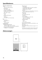
Schéma OUTPUT (HIGH PASS) OUTPUT (THRU) INPUT (+4dB) INPUT (+4dB) OUTPUT (THRU) OUTPUT (HIGH PASS) ch B ch A 100Hz HPF 100Hz HPF LOW BOOST SUM LOW CUT LPF LPF PHASE CUTOFF FREQ (80Hz to 100Hz) NORMAL REVERSE P.AMP BTL SPEAKER LEVEL Graphique de performance Bande passante standard +10 0 REPONSE (dB) -10 -20 -30 -40 20 100 FREQUENCE (Hz) Fr quence de coupure 100Hz 90Hz 80Hz 1k 13
-
 1
1 -
2
-
3
-
4
-
5
-
6
-
7
-
 8
8 -
 9
9 -
 10
10 -
 11
11 -
 12
12 -
 13
13 -
 14
14 -
 15
15 -
 16
16 -
 17
17 -
 18
18 -
19
-
20
-
21
-
22
-
23
-
24
-
25
-
26
 |
 |

13
Schéma
Graphique de performance
Bande passante standard
HPF
HPF
BOOST
LOW
CUT
LOW
LPF
LPF
SUM
(HIGH PASS)
OUTPUT
(THRU)
OUTPUT
(+4dB)
INPUT
(+4dB)
INPUT
(THRU)
OUTPUT
(HIGH PASS)
OUTPUT
100Hz
100Hz
PHASE
NORMAL
REVERSE
(80Hz to 100Hz)
CUTOFF FREQ
ch A
ch B
SPEAKER
P.AMP
LEVEL
BTL
Fr quence de coupure
FREQUENCE (Hz)
REPONSE (dB)
1k
100
20
-40
-30
-20
-10
0
+10
100Hz
90Hz
80Hz