Yamaha SWR2100P-10G SWR2100P-10G/SWR2100P-5G Owners Manual - Page 12
LINK/ACT indicator, SPEED indicator, PoE STATE indicator, SWR2100P-10G/SWR2100P-5G Owner's Manual
 |
View all Yamaha SWR2100P-10G manuals
Add to My Manuals
Save this manual to your list of manuals |
Page 12 highlights
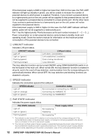
If the total power supply is 63W or higher but lower than 70W (in this case, the PoE LIMIT indicator will light up steadily in green), you will be unable to increase the number of powered devices to which power is supplied. Therefore, if you connect a powered device to a higher-priority port on the unit, power will be supplied to that powered device, but will not be supplied to a powered device connected to a lower-priority port. On the other hand, if you connect a powered device to a lower-priority port on the unit, power will not be supplied to that powered device. If the total power supply is 70W or higher (in this case, the PoE LIMIT indicator will flash green), power will not be supplied to a lower-priority port. Port 1 has the highest priority. Priority decreases as the port number increases (1 2 3 ...). Power consumption on certain powered devices varies between standby mode and operating mode. Check the owner's manual for information on the maximum power consumption of the powered devices to be connected. 3 LINK/ACT indicator Indicates LAN port status. LINK/ACT indicator Light off Light on (green) Flashing (green) Flashing (orange) LAN port status Link down. (unavailable) Link established. (available) Data is being transferred. Loop detected. The loop detection function can be turned ON/OFF using CONFIGURATION switch 4 on the front panel of the main unit. When turned ON, the loop detection function is enabled in all ports, and in the event of loop detection, communication from the corresponding port is automatically blocked. When turned OFF, the loop detection and blocking functions are disabled in all ports. 4 SPEED indicator Indicates the connection speed of the LAN port. SPEED indicator Light off Light on (orange) Light on (green) Connection status Not connected or connecting via 10BASE-T. Connecting via 100BASE-TX. Connecting via 1000BASE-T. 5 PoE STATE indicator Indicates the power supply status. PoE STATE indicator Light off Light on (green) Flashing (green) Power supply status Not supplying *1 Supplying Not supplying *2 *1 The indicator is also turned off if a device is not connected to the corresponding port; if the connected device does not need a power supply; or if power is not being supplied to the device due to a limitation in the unit's total power supply. *2 The indicator will flash green if power supply is suspended because the power output at the port has exceeded the maximum power supply allowed per port. The maximum power supply allowed per port varies depending on the power consumption class of the connected powered device. 12 SWR2100P-10G/SWR2100P-5G Owner's Manual
-
 1
1 -
2
-
3
-
4
-
5
-
6
-
 7
7 -
 8
8 -
 9
9 -
 10
10 -
 11
11 -
 12
12 -
 13
13 -
 14
14 -
 15
15 -
 16
16 -
 17
17 -
18
-
19
-
20
-
21
-
22
-
23
-
24
-
25
-
26
-
27
-
28
 |
 |
