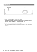
Yamaha SWR2100P-10G SWR2100P-10G/SWR2100P-5G Owners Manual - Page 15
Bottom panel, Rubber feet installation guide, Attachment holes for the rack-mount accessory
 |
View all Yamaha SWR2100P-10G manuals
Add to My Manuals
Save this manual to your list of manuals |
Page 15 highlights
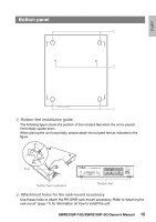
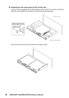
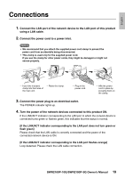
English Bottom panel A B A A Rubber feet installation guide The following figure shows the position of the included feet when the unit is placed horizontally upside-down. When placing the unit horizontally, please attach the included feet as indicated in the figure. Feet Rubber feet installation Rubber feet B Attachment holes for the rack-mount accessory Use these holes to attach the RK-SWR rack-mount accessory. Refer to "Attaching the rack mount" (page 17) for information on how to install the unit. SWR2100P-10G/SWR2100P-5G Owner's Manual 15
-
 1
1 -
2
-
3
-
4
-
5
-
6
-
7
-
8
-
9
-
 10
10 -
 11
11 -
 12
12 -
 13
13 -
 14
14 -
 15
15 -
 16
16 -
 17
17 -
 18
18 -
 19
19 -
 20
20 -
21
-
22
-
23
-
24
-
25
-
26
-
27
-
28
 |
 |
English
SWR2100P-10G/SWR2100P-5G Owner’s Manual
15
A
Rubber feet installation guide
The following figure shows the position of the included feet when the unit is placed
horizontally upside-down.
When placing the unit horizontally, please attach the included feet as indicated in the
figure.
B
Attachment holes for the rack-mount accessory
Use these holes to attach the RK-SWR rack-mount accessory. Refer to
“Attaching the
rack mount” (page 17)
for information on how to install the unit.
Bottom panel
A
B
A
Feet
Rubber feet
Rubber feet installation