Zenith L10V22 Operating Guide - Page 4
Controls, Supplied Accessories
 |
View all Zenith L10V22 manuals
Add to My Manuals
Save this manual to your list of manuals |
Page 4 highlights
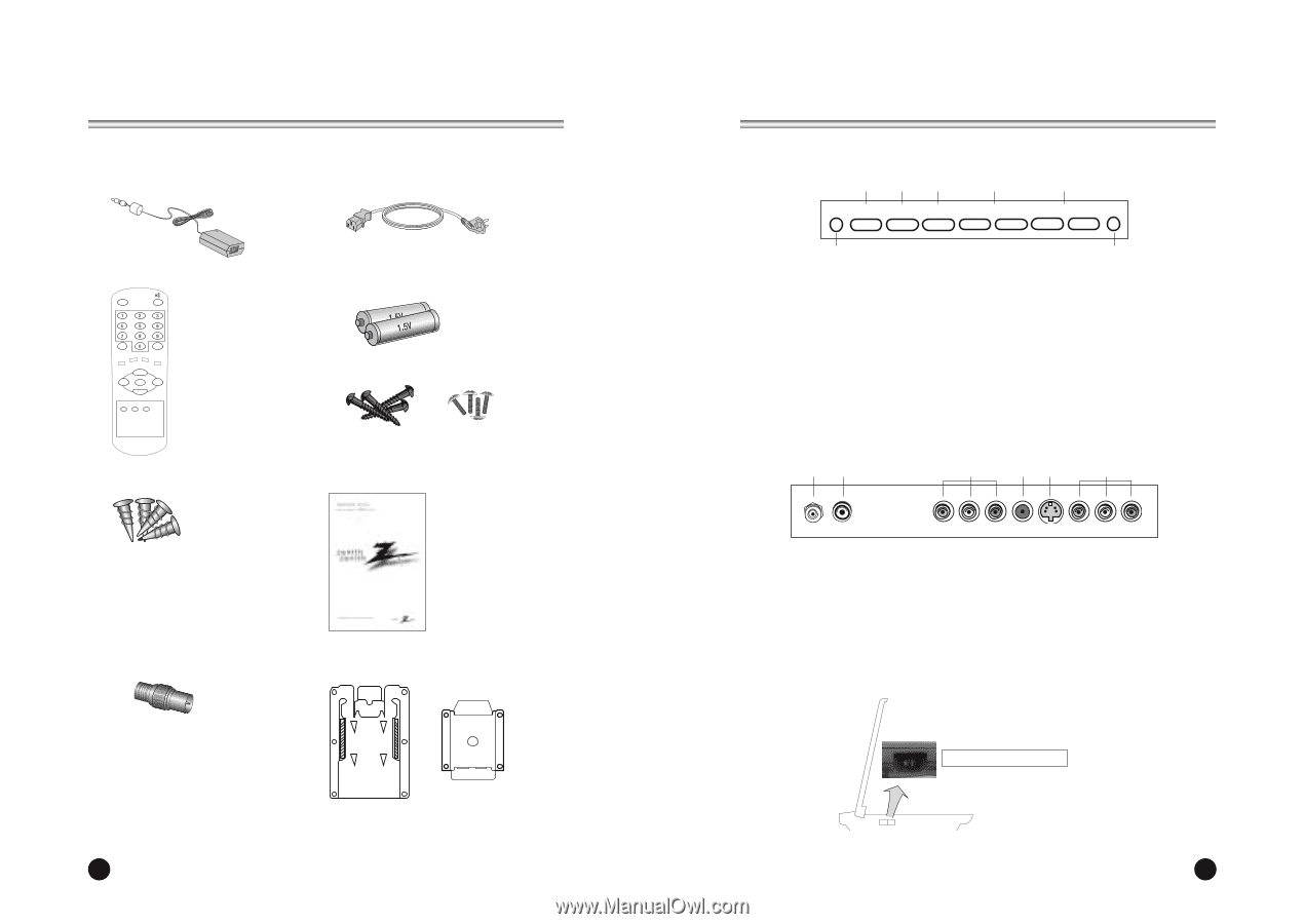
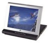
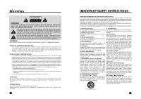
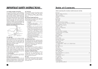
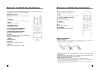
Supplied Accessories • Make sure all the accessories are included with TV. 1. DC Adapter 2. AC Cord 3. Remote Control POWER SSM PSM ST/SAP Q.VIEW MENU TV/AV PRV CVOL OK VOLB PRW CC MEMORY SLEEP 6. Plastic Drywall Anchors 4. Batteries (size AAA) 5. Metal Screws (2 Types) 7. Owner's Manual 8. Antenna Adapter 9. Brackets 6 Controls 23 4 POWER TV/AV MENU 5 - CH + 6 - VOL + 1 1. POWER/STANDBY INDICATOR Illuminates brightly when the set is in standby mode. Dims when the set is switched on. 2. POWER Turns the TV on and off. 3. TV/AV Selects TV, COMPONENT, VIDEO or SVIDEO modes. Clears the menu from the screen. 7 4. MENU Displays a menu. 5. + CH - (Channel Up/Down) Selects next channel or a menu option. 6. +VOL -(Volume Up/Down) Adjusts the sound level. Adjusts menu option settings 7. REMOTE CONTROL SENSOR 89 10 11 12 13 ANT. DC-12V COMPONENT INPUT H/P S-VIDEO AV-IN 8. Ant. (Antenna Input) 9. DC 12V Adapter input 10. COMPONENT INPUT 11. HEADPHONE Input Connect a headphone to this input. 12. S-VIDEO Input Connect the output of an S -VIDEO VCR to the S-VIDEO input. Connect the audio outputs of an S-VIDEO VCR to the AV-IN audio inputs. 13. A/V IN Inputs Connect the Audio/Video outputs of external equipment to these inputs. Main Power switch 7
-
 1
1 -
 2
2 -
 3
3 -
 4
4 -
 5
5 -
 6
6 -
 7
7 -
 8
8 -
 9
9 -
 10
10 -
11
-
12
 |
 |