3Com 3C17300A Implementation Guide
3Com 3C17300A - Switch 4200 Manual
 |
UPC - 662705493169
View all 3Com 3C17300A manuals
Add to My Manuals
Save this manual to your list of manuals |
3Com 3C17300A manual content summary:
- 3Com 3C17300A | Implementation Guide - Page 1
SuperStack® 3 Switch 4200 Family Implementation Guide Generic guide for units in the SuperStack 3 Switch 4200 Family: 3C17300 3C17302 3C17304 3C17300A 3C17302A 3C17304A http://www.3com.com/ Part No. DUA1730-0BAA03 Published June 2005 - 3Com 3C17300A | Implementation Guide - Page 2
any time. If there is any software on removable media described in this User Guide. Unless otherwise indicated, 3Com registered trademarks are registered in the United States and may or may not be registered in other countries. 3Com, the 3Com logo and SuperStack are all registered trademarks of 3Com - 3Com 3C17300A | Implementation Guide - Page 3
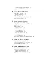
Software? 15 Switch Features Explained 15 Automatic IP Configuration 16 Security 16 Aggregated Links 16 Auto-negotiation 17 Multicast Filtering 18 Spanning Tree Protocol and Rapid Spanning Tree Protocol 18 Switch Database 19 Traffic Prioritization 19 RMON 20 Broadcast Storm Control 20 VLANs - 3Com 3C17300A | Implementation Guide - Page 4
44 How RSTP Differs to STP 45 STP Example 45 STP Configurations 46 Using STP on a Network with Multiple VLANs 48 5 USING THE SWITCH DATABASE What is the Switch Database? 49 How Switch Database Entries Get Added 49 Switch Database Entry States 50 6 USING TRAFFIC PRIORITIZATION What is Traffic - 3Com 3C17300A | Implementation Guide - Page 5
VLANs 66 VLANs and Your Switch 67 The Default VLAN 67 Communication Between VLANs 67 Creating New VLANs 68 VLANs: Tagged and Untagged Membership 68 Placing a Port in a Single VLAN 69 VLAN Configuration Examples 70 Using Untagged Connections 70 Using 802.1Q Tagged Connections 71 9 USING AUTOMATIC IP - 3Com 3C17300A | Implementation Guide - Page 6
Works 82 Auto VLAN Assignment 83 Important Considerations 83 What is Disconnect Unauthorized Device (DUD)? 85 How DUD Works 85 What is RADIUS? 85 11 USING SWITCH CONFIGURATION FEATURES Configuration Save and Restore 87 Upgrading Management Software 89 A CONFIGURATION RULES Configuration Rules for - 3Com 3C17300A | Implementation Guide - Page 7
D STANDARDS SUPPORTED GLOSSARY INDEX - 3Com 3C17300A | Implementation Guide - Page 8
- 3Com 3C17300A | Implementation Guide - Page 9
notes. Most user guides and release notes are available in Adobe Acrobat Reader Portable Document Format (PDF) or HTML on the 3Com World Wide Web site: http://www.3com.com/ Please note that when this Guide states "the Switch", this is a reference to all units in the SuperStack® 3 Switch 4200 Family. - 3Com 3C17300A | Implementation Guide - Page 10
Conventions Table 1 and Table 2 list conventions that are used throughout this guide. Table 1 Notice Icons Icon Notice Type Description Information note Information that describes important features or instructions Caution Information that alerts you to potential loss of data or potential - 3Com 3C17300A | Implementation Guide - Page 11
accompanies your Switch. Supplied in PDF format, this guide contains: ■ A list of the features supported by the Switch ■ A summary of the web interface operations and CLI commands that enable you to manage the Switch. ■ Release Notes These notes provide information about the current software release - 3Com 3C17300A | Implementation Guide - Page 12
■ Page number (if appropriate) Example: ■ SuperStack 3 Switch Implementation Guide ■ Part number: DUA1730-0BAA0x ■ Page 25 Please note that we can only respond to comments and questions about 3Com product documentation at this e-mail address. Questions related to technical support or sales should be - 3Com 3C17300A | Implementation Guide - Page 13
3 Using Multicast Filtering Chapter 4 Using Resilience Features Chapter 5 Using the Switch Database Chapter 6 Using Traffic Prioritization Chapter 7 Status Monitoring and Statistics Chapter 8 Setting Up Virtual LANs Chapter 9 Using Automatic IP Configuration Chapter 10 Making Your Network Secure - 3Com 3C17300A | Implementation Guide - Page 14
14 - 3Com 3C17300A | Implementation Guide - Page 15
Software? Switch Features Explained This chapter contains introductory information about the SuperStack® 3 Switch management software and supported features. It covers the following topics: ■ What is Management Software? ■ Switch Features Explained For detailed descriptions of the web interface - 3Com 3C17300A | Implementation Guide - Page 16
of the features supported by your Switch, please refer to the Management Quick Reference Guide supplied in PDF format on the CD-ROM that accompanies your Switch. Automatic IP Configuration By default the Switch tries to configure itself with IP information without requesting user intervention. It - 3Com 3C17300A | Implementation Guide - Page 17
maximum capabilities - these capabilities are by default the parameters that provide the highest performance supported by the port. For details of the auto-negotiation features supported by your Switch, please refer to the Management Quick Reference Guide supplied in PDF format on the CD-ROM that - 3Com 3C17300A | Implementation Guide - Page 18
multicast filtering system supported by your Switch uses IGMP (Internet default. RSTP can restore a network connection quicker than the STP feature. RSTP can detect if it is connected to a legacy device that only supports IEEE 802.1D STP and will automatically downgrade to STP on that particular port - 3Com 3C17300A | Implementation Guide - Page 19
Features". Switch Database The Switch Database is an integral part of the Switch and is used by the Switch to determine if a packet should be forwarded, and which port gets the highest level of service. The traffic prioritization feature supported by your Switch using layer 2 information, is - 3Com 3C17300A | Implementation Guide - Page 20
to: ■ Departmental groups ■ Hierarchical groups ■ Usage groups For more information about VLANs, see Chapter 8 "Setting Up Virtual LANs". Configuration Save and Restore Configuration Save and Restore allows the configuration of your Switch to be saved as a file on a remote server, or to be - 3Com 3C17300A | Implementation Guide - Page 21
Switch Features Explained 21 For further information about Configuration Save and Restore, see Chapter 11 "Using Switch Configuration Features". - 3Com 3C17300A | Implementation Guide - Page 22
22 CHAPTER 1: SWITCH FEATURES OVERVIEW - 3Com 3C17300A | Implementation Guide - Page 23
you require to manage the Switch please refer to the Management Interface Reference Guide supplied in HTML format on the CD-ROM that accompanies your Switch. Port Features The default state for all the features detailed below provides the best configuration for most users. In normal operation, you - 3Com 3C17300A | Implementation Guide - Page 24
all fixed ports on the Switch, or on a per port basis. You can also modify the capabilities that a port "advertises" on a per port basis, dependent on the type of port. For auto-negotiation to work, ports at both ends of the link must be set to auto-negotiate. GBIC or SFP ports do not support auto - 3Com 3C17300A | Implementation Guide - Page 25
on links where one end is at a fixed speed. The link will reset to the higher speed of operation when the link is lost or the unit is power cycled. ■ Smart auto-sensing can only be configured for the whole Switch and not on a per port basis. GBIC or SFP ports do not support smart auto-sensing. - 3Com 3C17300A | Implementation Guide - Page 26
, point-to-point redundancy between two devices (switch-to-switch or switch-to-server) that have full duplex connections operating at the same speed. By default, LACP is disabled on the 10/100/1000BASE-T and GBIC or SFP ports. If you enable LACP your Switch will detect if there is more than one - 3Com 3C17300A | Implementation Guide - Page 27
membership is detected by LACP, it will override the manual configuration. For example, in Figure 3, if a port on Switch C is physically connected to Switch B, but you manually configure the port on Switch C to be a member of an aggregated link for Switch A in error, LACP (if it is enabled) will - 3Com 3C17300A | Implementation Guide - Page 28
automatically determine the port membership for that aggregated link. The aggregated link may be manually configured with appropriate configuration settings, such as VLAN membership, to links in the aggregated link. By default LACP is disabled on all 10/100/1000BASE-T and GBIC or SFP Switch ports. - 3Com 3C17300A | Implementation Guide - Page 29
standby state until there is a problem with a higher speed link(s). The lower speed link(s) will then become active. ■ Note that the port security must be disabled on any port that is to become part of an aggregated link. It is not possible to configure this feature on a port that is a member of an - 3Com 3C17300A | Implementation Guide - Page 30
of an aggregated link but it will never be activated.) ■ If ports of a different speed are aggregated together, the higher speed links carry both ends of an aggregated link. For example, the configuration in Figure 4 will not work as Switch A has one aggregated link defined whose member links - 3Com 3C17300A | Implementation Guide - Page 31
links as efficiently as possible. To avoid the potential problem of out-of-sequence packets (or "packet re-ordering"), the Switch ensures that all the conversations between a given pair of endstations will pass through the same port in the aggregated link. Single-to-multiple endstation conversations - 3Com 3C17300A | Implementation Guide - Page 32
link between two Switch units Switch 4200 28-Port 4 Gbps Aggregated Link Switch 4200 28-Port To set up this configuration: 1 Add the 1000BASE-T ports on the upper unit to the aggregated link. 2 Add the 1000BASE-T ports on the lower unit to the aggregated link. 3 Add the SFP ports on the upper - 3Com 3C17300A | Implementation Guide - Page 33
Interface Reference Guide supplied in HTML format on the CD-ROM that accompanies your Switch. A multicast is a packet that is intended for "one-to-many" and "manyto-many" communication. Users explicitly request to participate in the communication by joining an endstation to a specific multicast - 3Com 3C17300A | Implementation Guide - Page 34
or collaborators expands. ■ Works with other IP protocols and services, such as Quality of Service (QoS). There are situations where a multicast register to join specific multicast groups. With multicast filtering, network devices only forward multicast traffic to the ports that are connected - 3Com 3C17300A | Implementation Guide - Page 35
by default on the Switch 4200 Family. This helps prevent interoperability issues with core products that may not follow the lowest IP address election method. You can enable or disable IGMP query mode for all Switch units in the stack using the queryMode command on the command line interface IGMP - 3Com 3C17300A | Implementation Guide - Page 36
command will configure the Switch 4200 Series to automatically negotiate with compatible devices on VLAN 1 to become the querier. The Switch 4200 Family is compatible with any device that conforms to the IGMP v2 protocol. IGMP Multicast Filtering IGMP is the system that all IP-supporting network - 3Com 3C17300A | Implementation Guide - Page 37
37 Management Interface Reference Guide supplied on your Switch CD-ROM. If IGMP multicast learning is not enabled then IP multicast traffic is always forwarded, that is, it floods the network. For information about configuring IGMP functionality on an endstation, refer to the user documentation - 3Com 3C17300A | Implementation Guide - Page 38
38 CHAPTER 3: USING MULTICAST FILTERING - 3Com 3C17300A | Implementation Guide - Page 39
feature. For detailed descriptions of the web interface operations and the command line interface (CLI) commands that you require to manage the Switch please refer to the Management Interface Reference Guide by default on your Switch. To be fully effective, STP must be enabled on all Switches in - 3Com 3C17300A | Implementation Guide - Page 40
more than 256 ports. ■ Support for Fast-Forwarding configuration of edge ports provided by the 'Fast Start' feature. Fast Start allows a port that is connected to an endstation to begin forwarding traffic after only four seconds; this "Auto" setting is default for front panel ports. During these - 3Com 3C17300A | Implementation Guide - Page 41
. STP detects the duplicate paths and prevents, or blocks, one of them from forwarding traffic, so this configuration will work satisfactorily. STP has determined that traffic from LAN segment 2 to LAN segment 1 can only flow through Bridges C and A, because, for example, this path - 3Com 3C17300A | Implementation Guide - Page 42
42 CHAPTER 4: USING RESILIENCE FEATURES Figure 8 Traffic flowing through Bridges which is the most efficient path between each bridged segment and a specifically assigned reference point on the network. Once the most efficient path has -evaluated the situation and opened the path through Bridge B. - 3Com 3C17300A | Implementation Guide - Page 43
outlined in the sections below. STP Requirements Before it can configure the network, the STP system requires: ■ Communication between all the less efficient the link. Table 3 shows the default port costs for a Switch. Table 3 Default port costs Port Speed Link Type Path Cost 802.1D-1998 Path - 3Com 3C17300A | Implementation Guide - Page 44
network changes, the first bridge to detect the change sends out an SNMP trap. CAUTION: Network loops can occur if aggregated links are manually configured incorrectly, that is, the physical connections do not match the assignment of ports to an aggregated link. RSTP and STP may not detect these - 3Com 3C17300A | Implementation Guide - Page 45
which is why RSTP can carry out automatic configuration and restore a link faster than STP. STP Example Figure 10 shows a LAN that has STP enabled. The LAN has three segments, and each segment is connected using two possible links. Figure 10 Port costs in a network ■ Bridge A has the lowest Bridge - 3Com 3C17300A | Implementation Guide - Page 46
is therefore selected as the Designated Bridge Port for LAN Segment 3. STP Configurations Figure 11 shows three possible STP configurations using SuperStack 3 Switch units. ■ Configuration 1 - Redundancy for Backbone Link In this configuration, the Switches both have STP enabled and are connected - 3Com 3C17300A | Implementation Guide - Page 47
Figure 11 STP configurations How STP Works 47 - 3Com 3C17300A | Implementation Guide - Page 48
VLAN configuration on your network takes into account the expected STP topology and alternative topologies that may result from link failures. For example, Figure 12 shows a network containing VLANs 1 and 2. They are connected using the 802.1Q-tagged link between Switch B and Switch C. By default - 3Com 3C17300A | Implementation Guide - Page 49
that sent the packet, the VLAN ID, and the port identifier on which the packet is received. ■ You can enter and update entries using the bridge addressDatabase CLI command, the Bridge > Address Database Web Interface operation, or an SNMP Network Manager, for example 3Com Network Supervisor. - 3Com 3C17300A | Implementation Guide - Page 50
, but they are still removed from the database if the Switch is reset or powered-down. ■ Permanent - The entry has been placed into the Switch Database using the management interface. Permanent entries are not removed from the Switch Database unless they are removed using the bridge addressDatabase - 3Com 3C17300A | Implementation Guide - Page 51
Management Interface Reference Guide supplied in HTML format on the CD-ROM that accompanies your Switch. The SuperStack 3 Switch 4200 Family has two traffic queues per port giving it a basic capability to prioritize traffic. For more granular prioritization and an enhanced Quality of Service support - 3Com 3C17300A | Implementation Guide - Page 52
level of service. The Switch employs two VLAN identification and user priority information. The information is carried in a header field immediately following the destination MAC address, and Source MAC address. 802.1D Priority Levels The traffic prioritization feature supported by the Switch - 3Com 3C17300A | Implementation Guide - Page 53
Low Priority Queue Egress Port High Priority Queue Figure 13 illustrates IEEE 802.1D traffic types as well as associated priority levels and how they are mapped to the two supported traffic queues. The 802.1D service level of the packet is not altered by the Switch 4200 Series. DiffServ traffic - 3Com 3C17300A | Implementation Guide - Page 54
Priority Queue All Egress Ports High Priority Queue Figure 14 illustrates how DiffServ code point (DSCP) service levels are mapped to the two Traffic Queues. The DSCP service level of the packet is not altered by the Switch 4200 Family. Traffic Prioritization and your Switch The traffic should be - 3Com 3C17300A | Implementation Guide - Page 55
detailed description of the commands that you require, refer to the Management Interface Reference Guide supplied in HTML format on the CD-ROM that accompanies your Switch. Configure Quality of service in the Switch 4200 Family in the following way: 1 Apply Traffic classification First identify the - 3Com 3C17300A | Implementation Guide - Page 56
to the port(s), the QoS configuration defined in the profile will immediately become active. Head of Line Blocking (HOL) You can adjust the Head of Line Blocking settings for Fast Ethernet ports to one of the following: ■ QoS - This is the default setting. Using this setting, the Switch uses - 3Com 3C17300A | Implementation Guide - Page 57
details of the features that assist you with status monitoring and statistics. For detailed descriptions of the web interface operations and the command line interface (CLI) commands that you require to manage the Switch please refer to the Management Interface Reference Guide supplied in HTML - 3Com 3C17300A | Implementation Guide - Page 58
variable. Alarms are used to inform you of network performance problems and they can trigger automated responses through the Events group. Events than having to watch real-time graphs for important occurrences, you can depend on the Event group for notification. Through the SNMP traps, events can - 3Com 3C17300A | Implementation Guide - Page 59
of RMON Using the RMON features of your Switch has three main advantages: ■ It improves your efficiency Using RMON allows you to remain at one workstation and collect information from widely dispersed LAN segments or VLANs. This means that the time taken to reach a problem site, set up equipment - 3Com 3C17300A | Implementation Guide - Page 60
RMON group Statistics History Alarms Events Support supplied by the Switch A new or initialized Switch has one Statistics session per port. A new or initialized Switch has two History sessions per port. These sessions provide the data for the Web interface history displays: ■ 30 second intervals - 3Com 3C17300A | Implementation Guide - Page 61
Software Upgrade report Action Send Trap. Block broadcast and multicast traffic on the port. Recovers with the unfilter port event. Send Trap. Turn port off. Send Trap. Turn port on. Turn port off. Turn port on. Send Trap. Stop blocking broadcast and multicast traffic on the port. The Default - 3Com 3C17300A | Implementation Guide - Page 62
to be displayed and then forwards it on to the SMS or pager gateway. You can configure the email address to which you wish the notifications to be sent. However, you cannot change the factory default notification messages for event emails. RMON traps continue to be sent, in addition to any email - 3Com 3C17300A | Implementation Guide - Page 63
RMON and the Switch 63 ■ A link fails or returns to service - you can select specific links that you wish to receive messages for, for example, a Execution of intrusion action ■ Authentication failure ■ POST Failed ports ■ Port access authentication failure ■ Port access logon ■ Port access logoff - 3Com 3C17300A | Implementation Guide - Page 64
64 CHAPTER 7: STATUS MONITORING AND STATISTICS - 3Com 3C17300A | Implementation Guide - Page 65
What are VLANs? ■ Benefits of VLANs ■ VLANs and Your Switch ■ VLAN Configuration Examples For detailed descriptions of the web interface operations and the command line interface (CLI) commands that you require to manage the Switch please refer to the Management Interface Reference Guide supplied in - 3Com 3C17300A | Implementation Guide - Page 66
any traditional network. Using VLANs also provides you with three other benefits: ■ VLANs ease the movement of devices users move to a different subnetwork, the addresses of each endstation must be updated manually. With a VLAN setup, if an endstation in VLAN Marketing for example is moved to a port - 3Com 3C17300A | Implementation Guide - Page 67
Switch contains a single VLAN, the Default VLAN. This VLAN has the following definition: ■ VLAN Name - Default VLAN ■ 802.1Q VLAN ID - 1 (if tagging is required) All the ports are initially placed in this VLAN, and it is the only VLAN that allows you to access the management software of the Switch - 3Com 3C17300A | Implementation Guide - Page 68
If you want to move a port from the Default VLAN to another VLAN, you must first define information about the new VLAN on your Switch. VLANs: Tagged and Untagged Membership Your Switch supports 802.1Q VLAN tagging, a system that allows traffic for multiple VLANs to be carried on a single physical - 3Com 3C17300A | Implementation Guide - Page 69
a link support IEEE 802.1Q. To create an 802.1Q tagged link: 1 Ensure that the device at the other end of the link uses the same 802.1Q tags as your Switch, that is, the same VLAN IDs are configured (note that VLAN IDs are global across the network). 2 Place the Switch ports in the required VLANs as - 3Com 3C17300A | Implementation Guide - Page 70
cannot communicate with each other. This provides additional security for your network. Figure 17 VLAN configuration example: Using untagged connections To set up the configuration shown in Figure 17: 1 Configure the VLANs Create VLAN 2 on the Switch. VLAN 1 is the default VLAN and already exists. - 3Com 3C17300A | Implementation Guide - Page 71
to Switch 2. Figure 18 VLAN configuration example: 802.1Q tagged connections To set up the configuration shown in Figure 18: 1 Configure the VLANs on Switch 1 Define VLAN 2. VLAN 1 is the default VLAN and already exists. 2 Add endstation ports on Switch 1 to the VLANs Place the endstation ports in - 3Com 3C17300A | Implementation Guide - Page 72
link to Switch 2. 4 Configure the VLANs on Switch 2 Define VLAN 2. VLAN 1 is the default VLAN and already exists. 5 Add endstation ports on Switch 2 to the VLANs Place the endstation ports in the appropriate VLANs as untagged members. 6 Add port 11 on Switch 2 to the VLANs Add port 11 on Switch 2 as - 3Com 3C17300A | Implementation Guide - Page 73
■ How Your Switch Obtains IP Information ■ How Automatic IP Configuration Works ■ Important Considerations For detailed information on setting up your Switch for management, see the Getting Started Guide that accompanies your Switch. For detailed descriptions of the web interface operations and the - 3Com 3C17300A | Implementation Guide - Page 74
to SNMP requests. How Automatic IP Configuration Works When your Switch is powered up for the first time the IP configuration setting is set to automatic - this is the default setting. If your Switch has been powered up before, whichever of the three options for IP configuration (manual, automatic - 3Com 3C17300A | Implementation Guide - Page 75
Auto-IP configuration feature. 2 The Auto-IP feature starts with an IP address of 169.254.100.100. It uses the Address Resolution Protocol (ARP) to check to make sure this address is not already in use on the network. If not, it will allocate this default address to the Switch. If this IP address - 3Com 3C17300A | Implementation Guide - Page 76
important points to note when using the automatic IP configuration feature. The dynamic nature of automatically configured IP information means that a Switch may change its IP address whilst in use. Event Log Entries and Traps An event log will be generated and an SNMP trap will be sent if any of - 3Com 3C17300A | Implementation Guide - Page 77
■ Auto VLAN Assignment ■ What is Disconnect Unauthorized Device (DUD)? ■ What is RADIUS? For detailed descriptions of the Web interface operations and the Command Line Interface (CLI) commands that you require to manage the Switch please refer to the Management Interface Reference Guide supplied in - 3Com 3C17300A | Implementation Guide - Page 78
10: MAKING YOUR NETWORK SECURE Port Security The Switch supports the following port security modes, which you can set for an individual port or a range of ports: ■ No Security Port security is disabled and all network traffic is forwarded through the port without any restrictions. ■ Continuous - 3Com 3C17300A | Implementation Guide - Page 79
known to be infected by a virus) and placed on a seperate 'safe' VLAN. ■ Rada Or Network Login (Mixed Secure Network Login and Rada-based Network different times, only some of which support 802.1X. It also allows a single port configuration to be used throughout a switch, regardless of the type of - 3Com 3C17300A | Implementation Guide - Page 80
network access, Network Login also allows the user of a port to be identified. This user identification information can be used for service accounting or billing, or to help network administrators resolve problems. Network Login is a feature that is particularly relevant in publicly accessible - 3Com 3C17300A | Implementation Guide - Page 81
access on each port that has switch-configured VLAN and QoS parameters. If default access has not been configured the switch will maintain port security settings. Figure 19 Network Login Operation Network Access Client (Client Device) Network Access Server (Switch 4200) Authentication Information - 3Com 3C17300A | Implementation Guide - Page 82
Radius Authenticated Device Access feature complements the existing 802.1X support of the Switch. Instead of needing an 802.1X client on every end station, the switch can use the MAC (Switch 4200) MAC address Authentication via MAC Address RADIUS Server For Rada, the Switch uses PAP (Password - 3Com 3C17300A | Implementation Guide - Page 83
Service-Type Value PPP Framed Auto VLAN Assignment Auto VLAN assignment complements the basic Network Login and Rada features. It allows an appropriate VLAN configuration to be obtained from a RADIUS server when a user or device authenticates on a port. The configuration obtained will be specific - 3Com 3C17300A | Implementation Guide - Page 84
to the default access. ■ Network Login and Rada are not supported on ports configured to operate as members of an aggregated link. ■ Some client devices that are connected to the Switch port may not support network login, for example printers. You should configure the Switch port to operate - 3Com 3C17300A | Implementation Guide - Page 85
port security feature Disconnect Unauthorized Device (DUD), disables a port if an unauthorized client device transmits data on it. DUD may be automatically enabled when a port User Service (RADIUS) is an industry standard protocol for carrying authentication, authorization and configuration - 3Com 3C17300A | Implementation Guide - Page 86
86 CHAPTER 10: MAKING YOUR NETWORK SECURE - 3Com 3C17300A | Implementation Guide - Page 87
CONFIGURATION FEATURES This chapter explains the configuration features supported by the Switch that aid ease of use and configuration of your network. It covers the following topics: ■ Configuration Save and Restore ■ Upgrading Management Software For detailed descriptions of the web interface - 3Com 3C17300A | Implementation Guide - Page 88
to that user level. Important Considerations ■ The Switch unit must be reset to its factory default settings before you can restore a configuration onto it. You can reset the Switch using the system control initialize CLI command or the System > Control > Initialize Web interface operation. ■ The - 3Com 3C17300A | Implementation Guide - Page 89
software on your Switch please refer to the Management Interface Reference Guide supplied in HTML format on the CD-ROM supplied with your Switch or on the 3Com Web site. CAUTION: 3Com strongly recommends that you use the TFTP Server as the primary means of upgrading your Switch. The Software Update - 3Com 3C17300A | Implementation Guide - Page 90
CHAPTER 11: USING SWITCH CONFIGURATION FEATURES has subsequently failed to power up correctly. The symptoms of a failed TFTP software upgrade are: the PowerOn Self Test (POST) has failed, the Power/Self Test LED is yellow, all of the Port Status LEDs are Off, you cannot access the Switch via Telnet. - 3Com 3C17300A | Implementation Guide - Page 91
II APPENDICES AND INDEX Appendix A Configuration Rules Appendix B Network Configuration Examples Appendix C IP Addressing Appendix D Standards Supported Glossary Index - 3Com 3C17300A | Implementation Guide - Page 92
92 - 3Com 3C17300A | Implementation Guide - Page 93
A CONFIGURATION RULES Configuration Rules for Gigabit Ethernet Gigabit Ethernet is designed to run over several media: ■ Single-mode fiber optic cable, with connections up to 5 km (3.1 miles). Support for distances over 5 km is supported depending on the module specification. ■ Multimode fiber - 3Com 3C17300A | Implementation Guide - Page 94
allow for large-scale Fast Ethernet networks. Figure 21 Fast Ethernet configuration rules The key topology rules are: ■ Maximum UTP cable length 412 m (1352 ft) fiber link is allowed for connecting switch-to-switch, or endstation-to-switch, using half-duplex 100BASE-FX. ■ A total network span of - 3Com 3C17300A | Implementation Guide - Page 95
plus a 100 m (328 ft) UTP link from a repeater out to the endstations. Configuration Rules with Full Duplex The Switch provides full duplex support for all its ports, including Expansion Module ports. Full duplex allows packets to be transmitted and received simultaneously and, in effect, doubles - 3Com 3C17300A | Implementation Guide - Page 96
96 APPENDIX A: CONFIGURATION RULES - 3Com 3C17300A | Implementation Guide - Page 97
B NETWORK CONFIGURATION EXAMPLES This chapter contains the following sections: ■ Simple Network Configuration Examples ■ Desktop Switch Example ■ Advanced Network Configuration Examples ■ Improving the Performance and Resilience of Your Network - 3Com 3C17300A | Implementation Guide - Page 98
EXAMPLES Simple Network Configuration Examples The following illustrations show some simple examples of how the Switch 4200 Family can be used in your network. Desktop Switch Example The example in Figure 22 shows how the Switch 4200 Family can be used for a group of users that require dedicated - 3Com 3C17300A | Implementation Guide - Page 99
Examples 99 Advanced Network Configuration Examples This section shows some network examples that illustrate how you can set up your network for optimum performance using some of the features supported by your Switch. Improving the Performance and Resilience of Your Network Figure 23 - 3Com 3C17300A | Implementation Guide - Page 100
100 APPENDIX B: NETWORK CONFIGURATION EXAMPLES - 3Com 3C17300A | Implementation Guide - Page 101
IP information that needs to be assigned to your Switch to enable you to manage it across a network. The topics covered are: ■ IP Addresses ■ Subnets and Subnet Masks ■ Default Gateways IP to your organization only, you may use any arbitrary IP address. 3Com suggests you use addresses in the series - 3Com 3C17300A | Implementation Guide - Page 102
and host parts depends on the class of IP network. IP addresses differ from Ethernet MAC addresses, which are unique hardware-configured 48-bit addresses. A central agency, such as the InterNIC Registration Services mentioned above, assigns the network part of the IP address, and you assign the host - 3Com 3C17300A | Implementation Guide - Page 103
fields are separated by dots. Figure 25 Dotted Decimal Notation for IP Addresses 10011110.01100101.00001010.00100000 = Binary notation 158.101.10. class that the central agency assigns to your network. The three primary classes of IP addresses are as follows: ■ Class A address - Uses 8 bits for the - 3Com 3C17300A | Implementation Guide - Page 104
IP network into sub-networks also known as subnets. Support for subnets is important because the number of bits assigned to the device part of an IP indicate the host part of the IP address, as shown in Figure 26. Figure 26 Subnet Masking IP address Take the IP address Network Subnet and Host - 3Com 3C17300A | Implementation Guide - Page 105
1 1 1 1 1 1 1 0 0 0 0 Result = subnet/host boundary Nentewtwoorkr Ssuubbnnet Host Using the Class B IP address from Figure 26 (158.101.230.52), the subnet mask is 255.255.255.240. The number that includes both Internet Service Providers (ISPs) now use this notation to denote the subnet mask. - 3Com 3C17300A | Implementation Guide - Page 106
. This hop-by-hop process continues until the IP packets reach the remote destination. If manually configuring IP information for the Switch, enter the IP address of the default gateway on the local subnet in which the Switch is located. If no default gateway exists on your network, enter the - 3Com 3C17300A | Implementation Guide - Page 107
by this version of Gigabit Multilayer Switching Software Table 12 Standards Supported. SNMP: SNMP Protocol (RFC 1157) MIB-II (RFC 1213) Bridge MIB (RFC 1493) RMON MIB II (RFC2021) Remote Monitoring MIB (RFC 1757) MAU MIB (RFC 2239) Administration: UDP (RFC 768) IP (RFC 791) ICMP (RFC 792) TCP - 3Com 3C17300A | Implementation Guide - Page 108
108 APPENDIX D: STANDARDS SUPPORTED - 3Com 3C17300A | Implementation Guide - Page 109
a group of ports to carry traffic between the switches. auto-negotiation A feature on twisted pair ports that allows them to advertise their capabilities for speed, duplex and flow control. When connected to a port that also supports auto-negotiation, the link can automatically configure itself to - 3Com 3C17300A | Implementation Guide - Page 110
map an IP address to a given MAC address each time a device is started. In addition, the protocol can assign the subnet mask and default objects locally to users and serves them to users when requested. Switch then groups classified traffic in order to schedule them with the appropriate service - 3Com 3C17300A | Implementation Guide - Page 111
level of service required by the packet across a network. DUD Disconnect Unauthorized Device. A port security feature that disables a port if an unauthorized client device transmits data on it. endstation A computer, printer or server that is connected to a network. Ethernet A LAN specification - 3Com 3C17300A | Implementation Guide - Page 112
link. gateway See router. GBIC Gigabit Interface Converter. Gigabit Ethernet IEEE standard 802. defines VLAN tagging. IEEE 802.3x A standard that defines a system of flow control for ports that IP networks. In the network management area, this group is responsible for the development of the SNMP - 3Com 3C17300A | Implementation Guide - Page 113
Switch, that optimizes the flow of multicast traffic. The device listens for IGMP messages and build mapping wishes to receive transmissions addressed to a specific multicast group. Based on group membership network using Internet protocols such as web services, TCP/IP, HTTP and HTML. An Intranet is - 3Com 3C17300A | Implementation Guide - Page 114
(SNMP) to gather information about the devices on a network. The Switch contains its own internal MIB. multicast A packet sent to a specific group A port security feature that controls user access at the network edge by blocking or unblocking access on a per-port basis. NIC Network Interface Card. - 3Com 3C17300A | Implementation Guide - Page 115
Radius Authenticated Device Access. This feature uses a device MAC address for authentication against a RADIUS server. RADIUS Remote Authentication Dial-In User Service. An industry standard protocol for carrying authentication, authorization and configuration information between a network device - 3Com 3C17300A | Implementation Guide - Page 116
how the Switch treats classified packets. The Switch offers some predefined standard service levels, for example, best effort, business critical, network control, and so on. SLIP Serial Line Internet Protocol. A protocol that allows IP to run over a serial line (console port) connection. SMTP - 3Com 3C17300A | Implementation Guide - Page 117
A TCP/IP application protocol that provides a virtual terminal service, letting a user log into another computer system and access a device as if the user were connected directly to the device. TFTP Trivial File Transfer Protocol. Allows you to transfer files (such as software upgrades) from - 3Com 3C17300A | Implementation Guide - Page 118
118 GLOSSARY Webcache A device that is installed on the network to cache frequently accessed Web pages from which they can be retrieved, thus reducing network traffic over the WAN. - 3Com 3C17300A | Implementation Guide - Page 119
maximum length 94, 95 Capture (RMON group) 60 Configuration Restore 20, 87 Save 20, 87 conventions notice icons, About This Guide 10 text, About This Guide 10 D default gateway 106 Default VLAN 67 Designated Bridge 44 Designated Bridge Port 44 DHCP 16, 74 Disconnect Unauthorized Device (DUD) 16 - 3Com 3C17300A | Implementation Guide - Page 120
costs permanent SDB entries 50 port costs, default 43 port security 16, 77, 78 priority in STP 43 priority levels 802.1D 52 Q QoS apply QoS profile 56 configuring traffic on a Switch 4200 55 creating profiles 56 How traffic is processed to provide QoS 55 service levels 55 traffic classification 55 - 3Com 3C17300A | Implementation Guide - Page 121
802.1D 52 traffic prioritization 51 802.1D 52 Trusted IP 85 U upgrade software 89 Upgrading Flash Images 89 Upgrading Management Software 89 Upgrading the Switch 4400 SE 89 V VLANs 65 802.1Q tagging 69 benefits 66 communication between 67 Default 67 defining the information for 68 IEEE 802.1Q 67 - 3Com 3C17300A | Implementation Guide - Page 122
122 INDEX
-
 1
1 -
 2
2 -
 3
3 -
 4
4 -
 5
5 -
 6
6 -
 7
7 -
8
-
9
-
10
-
11
-
12
-
13
-
14
-
15
-
16
-
17
-
18
-
19
-
20
-
21
-
22
-
23
-
24
-
25
-
26
-
27
-
28
-
29
-
30
-
31
-
32
-
33
-
34
-
35
-
36
-
37
-
38
-
39
-
40
-
41
-
42
-
43
-
44
-
45
-
46
-
47
-
48
-
49
-
50
-
51
-
52
-
53
-
54
-
55
-
56
-
57
-
58
-
59
-
60
-
61
-
62
-
63
-
64
-
65
-
66
-
67
-
68
-
69
-
70
-
71
-
72
-
73
-
74
-
75
-
76
-
77
-
78
-
79
-
80
-
81
-
82
-
83
-
84
-
85
-
86
-
87
-
88
-
89
-
90
-
91
-
92
-
93
-
94
-
95
-
96
-
97
-
98
-
99
-
100
-
101
-
102
-
103
-
104
-
105
-
106
-
107
-
108
-
109
-
110
-
111
-
112
-
113
-
114
-
115
-
116
-
117
-
118
-
119
-
120
-
121
-
122
 |
 |

Part No. DUA1730-0BAA03
Published June 2005
SuperStack
®
3
Switch 4200 Family
Implementation Guide
Generic guide for units in the SuperStack 3 Switch 4200 Family:
3C17300
3C17302
3C17304
3C17300A
3C17302A
3C17304A