3Com 3C888 User Guide - Page 45
This completes the Dual 56K LAN Modem installation. You are ready to go on
 |
UPC - 662705326443
View all 3Com 3C888 manuals
Add to My Manuals
Save this manual to your list of manuals |
Page 45 highlights
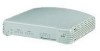
Before You Start the Installation 45 5 Connect the power supply to the back of the unit, as shown in Figure 28. 2 LINE 1 PHONE 1 LINE 2 P 1 4 3 LAN RESET 100¥-188AVMDACX 5 6 Figure 28 Power Cable Connection 6 Plug the other end of the power module into a surge-protected, standard wall outlet, and watch for the following front panel LED signals: s The PWR and AA indicator LEDs light up. s The ALERT LED flashes momentarily as the unit undergoes a power-up, self-test diagnostic. s After the diagnostic test has been completed, only the PWR LED remains lit. 7 Turn on your workstation. Watch for the LAN Status LED to flash and then remain lit. Alert Message AA Power Message MODEM 1 OH SD RD CD AA MODEM 1 CD MODEM 2 OH SD RD CD AA RD SD TX COLL LAN Status 2 Off1iceConnect 3 Dual 4 56k LAN Modem OH Power Alert MODEM 2 AA CD RD SD OH LAN Status TX COLL 1 2 3 4 OfficeConnect Dual 56k LAN Modem This completes the Dual 56K LAN Modem installation. You are ready to go on to Chapter 5 to configure the LAN Modem for shared access to the Internet. Or, if you wish to configure the LAN Modem for shared dial-out access to a Private Network, such as a remote corporate office LAN, refer to Chapter 6. To configure the LAN Modem for dial-in support, refer to Chapter 8. If the installation was not successful, refer to Chapter 10, "Troubleshooting and Maintenance."
-
 1
1 -
2
-
3
-
4
-
5
-
6
-
7
-
8
-
9
-
10
-
11
-
12
-
13
-
14
-
15
-
16
-
17
-
18
-
19
-
20
-
21
-
22
-
23
-
24
-
25
-
26
-
27
-
28
-
29
-
30
-
31
-
32
-
33
-
34
-
35
-
36
-
37
-
38
-
39
-
 40
40 -
 41
41 -
 42
42 -
 43
43 -
 44
44 -
 45
45 -
 46
46 -
 47
47 -
 48
48 -
 49
49 -
 50
50 -
51
-
52
-
53
-
54
-
55
-
56
-
57
-
58
-
59
-
60
-
61
-
62
-
63
-
64
-
65
-
66
-
67
-
68
-
69
-
70
-
71
-
72
-
73
-
74
-
75
-
76
-
77
-
78
-
79
-
80
-
81
-
82
-
83
-
84
-
85
-
86
-
87
-
88
-
89
-
90
-
91
-
92
-
93
-
94
-
95
-
96
-
97
-
98
-
99
-
100
-
101
-
102
-
103
-
104
-
105
-
106
-
107
-
108
-
109
-
110
-
111
-
112
-
113
-
114
-
115
-
116
-
117
-
118
-
119
-
120
-
121
-
122
-
123
-
124
-
125
-
126
-
127
-
128
-
129
-
130
-
131
-
132
-
133
-
134
-
135
-
136
-
137
-
138
-
139
-
140
-
141
-
142
-
143
-
144
-
145
-
146
-
147
-
148
-
149
-
150
-
151
-
152
-
153
-
154
-
155
-
156
-
157
-
158
-
159
-
160
-
161
-
162
-
163
-
164
-
165
-
166
-
167
-
168
 |
 |
