3Com 3CBLSG48 User Guide
3Com 3CBLSG48 - Baseline Switch 2948-SFP Manual
 |
UPC - 662705518947
View all 3Com 3CBLSG48 manuals
Add to My Manuals
Save this manual to your list of manuals |
3Com 3CBLSG48 manual content summary:
- 3Com 3CBLSG48 | User Guide - Page 1
3Com® Baseline Switch 2948-SFP Plus User Guide 3CBLSG48 www.3Com.com Part Number 10016089 Rev. AA Published July 2007 - 3Com 3CBLSG48 | User Guide - Page 2
not to remove or deface any portion of any legend provided on any licensed program or documentation contained in, or delivered to you in conjunction with, this User Guide. Unless otherwise indicated, 3Com registered trademarks are registered in the United States and may or may not be registered in - 3Com 3CBLSG48 | User Guide - Page 3
ABOUT THIS GUIDE This guide provides information about the Web user interface for the 3Com® Baseline Switch 2948-SFP Plus. The Web interface is a network management system that allows you to configure, monitor, and troubleshoot your switch from a remote web browser. The Web interface web pages are - 3Com 3CBLSG48 | User Guide - Page 4
VLANs. VLANs are logical subgroups with a Local Area Network (LAN) which combine user stations and network devices into a single virtual LAN segment, regardless of the physical LAN segment to which they are attached. Configuring IP of Service - Provides information defining Quality of Service, - 3Com 3CBLSG48 | User Guide - Page 5
. Warning Information that alerts you to potential Personal injury. Related Documentation In addition to this guide, other documentation available for the 3Com Baseline Switch 2948 includes: Safety and Support Information: Provides installation, set-up, and regulatory compliance information. - 3Com 3CBLSG48 | User Guide - Page 6
18 Setting Up SNMP Management V1 or V2 19 Default Users and Passwords 20 Upgrading Software using theCLI 20 2 USING THE 3COM WEB INTERFACE Starting the 3Com Web Interface 21 Understanding the 3Com Web Interface 23 Saving the Configuration 31 Resetting the Device 32 Restoring Factory Defaults - 3Com 3CBLSG48 | User Guide - Page 7
Viewing System Description 84 Configuring System Name Information 86 Configuring System Time 87 6 CONFIGURING PORTS Viewing Port Settings 90 Defining Port Settings 93 Viewing Port Details 95 7 AGGREGATING PORTS Viewing Link Aggregation 98 Configuring Link Aggregation 99 Modifying Link - 3Com 3CBLSG48 | User Guide - Page 8
LACP 103 Defining LACP Priority 104 Defining LACP Port 105 8 CONFIGURING VLANS VLAN Overview 106 Viewing VLAN Details 108 Viewing VLAN Port Details 109 Creating VLANs 110 Rename the VLANS 111 Modifying VLAN Settings 112 Modifying Port VLAN Settings 114 Removing VLANs 115 9 CONFIGURING IP - 3Com 3CBLSG48 | User Guide - Page 9
v2c 142 Defining SNMP Communities 143 Removing SNMP Communities 145 Defining SNMP Traps 146 Removing SNMP Traps 147 13 Configuring quALITY OF SERVICES Viewing CoS Settings 150 Defining CoS 151 Defining Queuing Algorithm 152 Viewing CoS to Queue 153 Defining CoS to Queue 153 Viewing DSCP to - 3Com 3CBLSG48 | User Guide - Page 10
3Com Network Supervisor 184 3Com Network Director 185 3Com Network Access Manager 185 3Com Enterprise Management Suite 186 Integration Kit with HP OpenView Network Node Manager 186 B device specifications and features Related Standard 187 Environmental 187 Physical 187 Electrical 188 Switch - 3Com 3CBLSG48 | User Guide - Page 11
TROUBLESHOOTING Problem Management 196 Troubleshooting Solutions 196 E 3COM CLI REFERENCE GUIDE Getting Started with the Command Line Interface 199 CLI Commands 200 F GLOSSARy ...210 G OBTAINING SUPPORT FOR YOUR 3COM PRODUCTS Register Your Product to Gain Service Benefits 216 Solve Problems - 3Com 3CBLSG48 | User Guide - Page 12
about the 3Com® Baseline Switch 2948-SFP Plus and how they can be used in your network. It covers summaries of the hardware and software features, and the following topics: About the Switch 2948 Front Panel Detail LED Status Indicators System Specifications Installing the Switch Setting Up for - 3Com 3CBLSG48 | User Guide - Page 13
converged network. The Switch 2948 includes the following model: Baseline Switch 2948-SFP Plus 48-Port The Switch 2948 features the following advantages: Full Gigabit speed access ports Jumbo frames Port security Link aggregation control protocol (LACP) Up to 256 VLANs Access control lists (ACLs - 3Com 3CBLSG48 | User Guide - Page 14
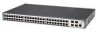
Supports fiber Gigabit Ethernet long-wave (LX), and fiber Gigabit Ethernet short-wave (SX) transceivers in any combination. Mounting 19-inch rack or standalone mounting Front Panel Detail Figure 1 shows the front panel of the Switch 2948-SFP Plus 48-Port unit. Figure 1 Switch 2948 SFP - 3Com 3CBLSG48 | User Guide - Page 15
STARTED LED Status Indicators The 2948-SFP Plus 48-Port Ethernet switches provide LED indicators on the front panel for your convenience to monitor the switch. Table 2 Describes the meanings of the LED. Table 2 Description on the LEDs of the Switch 2948 LED Label Status Description Power - 3Com 3CBLSG48 | User Guide - Page 16
specifications of the Switch 2948. Table 3 System specifications of the Switch 2948 switch Specification Switch 2948-SFP Plus 48-Port 3CBLSG48 Physical dimensions 44×440×265 mm (1.73 X 1.7.3 X 10.43 in.) (H×W×D) Weight 2.0 kg (4.4 lbs) Console port One Console port Gigabit Ethernet - 3Com 3CBLSG48 | User Guide - Page 17
you need to install and set up your 3Com switch. WARNING: Safety Information. Before you install or remove any components from the Switch or carry out any maintenance procedures, you must read the 3Com Switch Family Safety and Regulatory Information document enclosed. AVERTISSEMENT: Consignes de - 3Com 3CBLSG48 | User Guide - Page 18
to manage a switch. It covers the following topics: Methods of Managing a Switch Switch Setup Overview Manually set the IP Address using the Console Port Viewing IP Information using the Console Port Setting Up Web Interface Management Setting Up SNMP Management V1 or V2 Default Users and Passwords - 3Com 3CBLSG48 | User Guide - Page 19
Line Interface through the Console port for basic operations of the switch including setting and viewing the IP address, configuring user accounts, upgrading switch firmware, and more. Refer to "3Com CLI Reference Guide" on page 195. Web Interface Each switch has an internal set of web pages - 3Com 3CBLSG48 | User Guide - Page 20
can manage a switch using any network management workstation running the Simple Network Management Protocol (SNMP) as shown in Figure 3. For example, you can use the 3Com Network Director software, available from the 3Com website. Figure 3 SNMP Management over the Network Refer to "Setting Up SNMP - 3Com 3CBLSG48 | User Guide - Page 21
when it is in its default state. The whole setup process is summarized in Figure 4. Detailed procedural steps are contained in the sections that follow. In brief, you need to: Configure IP information manually for your switch or view the automatically configured IP information Prepare for your - 3Com 3CBLSG48 | User Guide - Page 22
Diagram CAUTION: To protect your switch from unauthorized access, you must change the default password as soon as possible, even if you do not intend to actively manage your switch. For more information on default users and changing default passwords, see "Default Users and Passwords" on page 20. - 3Com 3CBLSG48 | User Guide - Page 23
automatically using DHCP, or manually using values you assign. Automatic IP Configuration using DHCP By default the switch tries to configure its IP Information without requesting user intervention. It tries to obtain an IP address from a DHCP server on the network. Default IP Address If no DHCP - 3Com 3CBLSG48 | User Guide - Page 24
management. Work through the "Viewing IP Information using the Console Port" on page 17. Manual IP Configuration When you configure the IP information manually, the switch remembers the information that you enter until you change it again. You should use the Manual IP configuration method if: You do - 3Com 3CBLSG48 | User Guide - Page 25
can access the switch through the Console port to manually set the IP address, or to view the IP address that was assigned automatically (for example, by a DHCP server). For more information about the CLI, refer to "3Com CLI Reference Guide". Connecting to the Console Port This section describes - 3Com 3CBLSG48 | User Guide - Page 26
connector to the Console port of the switch b Attach the other end of the cable to the workstation. 2 Open your terminal emulation software and configure the COM port settings to which you have connected the cable. The settings must be set to match the default settings for the switch, which are: 38 - 3Com 3CBLSG48 | User Guide - Page 27
to manually set up the switch with IP information using the command line interface. You need to have the following information: IP address subnet mask default gateway 1 Connect to the switch Console port as described in "Connecting to the Console Port" page 14. 2 The command line interface login - 3Com 3CBLSG48 | User Guide - Page 28
14. The automatic IP configuration process usually completes within one minute. 2 The command line interface login sequence begins as soon as the switch detects a connection to its console port. 3 At the login prompt, enter admin as your user name and press Return. 4 At the password prompt, press - 3Com 3CBLSG48 | User Guide - Page 29
have already set up the switch with IP information as described in "Methods of Managing a Switch" on page 8. Ensure that the switch is connected a browser by default. You will only need to enable them if you have changed your browser settings. The switch's Web interface supports both secure ( - 3Com 3CBLSG48 | User Guide - Page 30
: http://xxx.xxx.xxx.xxx 5 At the login and password prompts, enter admin as your user name and press Return at the password prompt (or the password of your choice if you have already modified the default passwords). The main Web interface page is displayed. Setting Up SNMP Management V1 or V2 You - 3Com 3CBLSG48 | User Guide - Page 31
The default user is listed in Table 5. Table 5 Default Users Default User Name Password Access Level Admin (no password) Management - The user can access and change all manageable parameters Use the admin default user name (no password) to login and carry out initial switch - 3Com 3CBLSG48 | User Guide - Page 32
is required from each user. Two access levels exist on the 3Com Web Interface: ■ Management access level - Provides the user with read/write access. There is always one management level user configured for the switch. The factory default is be username: admin with no Password. Monitor access level - 3Com 3CBLSG48 | User Guide - Page 33
. The Enter Network Password Page opens: Figure 6 Enter Network Password Page 3 Enter your user name and password. The device default factory settings is configured with a User Name that is admin and a password that is blank. Passwords are case sensitive. 4 Click Login. The 3Com Web Interface Home - 3Com 3CBLSG48 | User Guide - Page 34
CHAPTER 2: USING THE 3COM WEB INTERFACE 23 Figure 7 3Com Web Interface Home Page Understanding the 3Com Web Interface The 3Com Web Interface Home Page contains the following views: Tab View - Provides the device summary configuration located at the top of the home page. Tree View - - 3Com 3CBLSG48 | User Guide - Page 35
24 CHAPTER 2: USING THE 3COM WEB INTERFACE Figure 8 Web Interface Components The following table lists the user interface components with their corresponding numbers: Table 6 Interface Components View 1 Tree View 2 Tab View 3 Web Interface Description Tree View provides easy - 3Com 3CBLSG48 | User Guide - Page 36
- Provides an explanation of the user inter face buttons, including both management buttons and task icons. Using the Web Interface Management Buttons - Provides instructions for adding, modifying, and deleting configuration parameters. The 3Com Web Interface Home Page contains a graphical - 3Com 3CBLSG48 | User Guide - Page 37
an easy method of configuring device information: Table 7 3Com Web Interface Configuration Buttons Button Button Name Description Create changes to the device. Delete Deletes configuration settings. Table 8 3Com Web Interface Information Tabs Tab Tab Name Description - 3Com 3CBLSG48 | User Guide - Page 38
WEB INTERFACE 27 Using Screen and Table Options 3Com contains screens and tables for configuring devices. This section contains the following topics Information To view configuration information: 1 Click Port > Administration > Summary. The Port Settings Summary Page opens. Figure 10 Port - 3Com 3CBLSG48 | User Guide - Page 39
WEB INTERFACE Adding Configuration Information The IP Setup Page enables you to add User-defined information to specific 3Com Web Interface pages. For example, to configure IP Setup: 1 Click Administration > IP Setup. The IP Setup Page opens. Figure 11 IP Setup Page 2 Enter the requisite information - 3Com 3CBLSG48 | User Guide - Page 40
CHAPTER 2: USING THE 3COM WEB INTERFACE 29 Modifying Configuration Information 1 Click Administration > System Access > Modify. The System Access Modify Page opens. Figure 12 System Access Modify Page 2 Modify the fields. 3 Click Apply. The access fields are modified. - 3Com 3CBLSG48 | User Guide - Page 41
30 CHAPTER 2: USING THE 3COM WEB INTERFACE Removing Configuration Information 1 Click Administration > System Access > Remove. The System Access Remove Page opens. Figure 13 System Access Remove Page 2 Select the user account to be deleted. 3 Click Remove. The user account is deleted, and the device - 3Com 3CBLSG48 | User Guide - Page 42
Saving the Configuration CHAPTER 2: USING THE 3COM WEB INTERFACE 31 Configuration changes are only saved to the device once the user saves the changes to the flash memory. The Save Configuration tab allows the latest configuration to be saved to the flash memory. To save the device configuration: - 3Com 3CBLSG48 | User Guide - Page 43
all user-defined changes to the flash memory before resetting the device. To reset the device: 1 Click Administration > Reset. The Reset Page opens. Figure 15 Reset Page 2 Click Reboot. A confirmation message is displayed. 3 Click OK. The device is reset, and a prompt for a user name and password - 3Com 3CBLSG48 | User Guide - Page 44
CHAPTER 2: USING THE 3COM WEB INTERFACE 33 Figure 16 User Name and Password Page 4 Enter a user name and password to reconnect to the web interface. - 3Com 3CBLSG48 | User Guide - Page 45
with Current IP Address - Resets the device with the factory default settings, but maintains the current IP Address, subnet mask, and default gateway address. Initialize with Default IP Address - Resets the device with the factory default settings, including the factory default IP Address. 2 Click - 3Com 3CBLSG48 | User Guide - Page 46
CHAPTER 2: USING THE 3COM WEB INTERFACE 35 Logging Off the Device To log off the device: 1 Click Logout. The Logout Page opens. 2 The following message appears: 3 Click OK. The 3Com Web Interface Home Page closes. - 3Com 3CBLSG48 | User Guide - Page 47
This section contains information about viewing basic settings available from the Web interface home page, including the Device , and software, boot, and hardware versions. To view the Device Summary Settings: 1 Click Device Summary. The Device Summary Page opens. Figure 18 Device Summary Page - 3Com 3CBLSG48 | User Guide - Page 48
SETTINGS 37 The Device Summary Page contains the following fields: Product Description - Displays the device model number and name. System Name - Defines the user Number - Displays the 3Com device 3C number. amount of time since the most recent device reset. The system time is displayed in the - 3Com 3CBLSG48 | User Guide - Page 49
38 CHAPTER 3: VIEWING BASIC SETTINGS Viewing Color Keys The Color Key Page provides information about the RJ45 or SFP port status. To view color keys: 1 Click Device Summary > Color Key. The Color Key Page opens. Figure 19 Color Key Page The Color Key Page - 3Com 3CBLSG48 | User Guide - Page 50
Maximum speed 10/100/1000M RJ45 or RJ45 SFP. Indicates that a link was detected. Light Blue SX/LX SFP. Indicates that a link was detected. Light Gray Port has been set to inactive by User or Protocol. Dark Blue Port has been selected by user. Red Port or Transceiver has failed POST or - 3Com 3CBLSG48 | User Guide - Page 51
4 MANAGING DEVICE SECURITY The Management Security section provides information for configuring system access, defining RADIUS authentication, port-based authentication and defining access control lists. This section includes the following topics: Configuring System Access Defining RADIUS - 3Com 3CBLSG48 | User Guide - Page 52
is required from each user. Two access levels exist on the 3Com Web Interface: Management access level - Provides the user with read/write access. There is always one management level user configured for the switch. The factory default is user name: admin with no Password. Monitor access level - 3Com 3CBLSG48 | User Guide - Page 53
42 CHAPTER 4: MANAGING DEVICE SECURITY Viewing System Access Settings The System Access Summary Page displays the current users and access levels defined on the device. To view System Access settings: 1 Click Administration > System Access > Summary. The System Access Summary Page opens. Figure 20 - 3Com 3CBLSG48 | User Guide - Page 54
with read and write access rights. Monitor - Provides users with read access rights. Password - Defines the user password. User passwords can contain up to 8 characters. Confirm Password - Verifies the password. 2 Define the fields. 3 Click Apply. The Users are created, and the device is updated. - 3Com 3CBLSG48 | User Guide - Page 55
Modify - Changes a password for an existing user. Password - Defines the local user password. Local user pass words can contain up to 8 characters. Confirm Password - Verifies the password. 2 Select a User Name to be modified. 3 Modify the fields. 4 Click Apply. The User settings are modified, and - 3Com 3CBLSG48 | User Guide - Page 56
The System Access Remove Page contains the following fields: Remove User(s) - Select user(s) from the list below to be removed. User Name - Displays the user name. Access Level - Displays the user access level. The lowest user access level is Monitoring and the highest is Management. Management - 3Com 3CBLSG48 | User Guide - Page 57
User Service (RADIUS) servers provide additional security for networks. RADIUS servers provide a centralized authentication method for 802.1X. The default parameters are user- Backup Server - Defines the RADIUS Backup Server authentication fields. Host IP Address - Defines the RADIUS Server - 3Com 3CBLSG48 | User Guide - Page 58
before retrying the query, or switching to the next server. Possible field values are 1-30. The default value is 3. Dead Time - Defines the default amount of time (in minutes) that a RADIUS server is bypassed for service requests. The range is 02000. The default value is 0. Key String - Defines - 3Com 3CBLSG48 | User Guide - Page 59
-based authentication authenticates users on a per-port basis via an external server. Only authenticated and approved system users can transmit and and indicates whether the supplicant is authorized to access system services. Port-based authentication creates two access states: Controlled Access - 3Com 3CBLSG48 | User Guide - Page 60
network administrator to view port-based authentication settings. To view Port-based Authentication: User Name - Displays the supplicant user name. Current Port Control - Displays the current port authorization state. Guest VLAN VLAN. Disabled - Disables an unauthorized port to join the Guest VLAN - 3Com 3CBLSG48 | User Guide - Page 61
in which the selected port is reauthenticated. The field default is 3600 seconds. Authenticator State - Displays the current global settings on the device and defining specific 802.1X setting for each port individually. Monitor users have no access to this page. To configure 802.1X Settings: - 3Com 3CBLSG48 | User Guide - Page 62
fields: 802.1X Global Settings Port Based Authentication State device. This is the default value. Authentication Method the port. Enable Guest VLAN - Provides limited network access VLAN is enabled, the port receives limited network access. For example, a network administrator can use Guest VLANs - 3Com 3CBLSG48 | User Guide - Page 63
device cannot provide authentication services to the client through the interface. Guest VLAN - Specifies whether the Guest VLAN is enabled on the port is reauthenticated. The field default is 3600 seconds. 2 Define the fields. 3 Click Apply. The 802.1X Settings are enabled, and the device - 3Com 3CBLSG48 | User Guide - Page 64
are forwarded or dropped. This section includes the following topics: Viewing MAC Based ACLs Configuring MAC Based ACLs Removing MAC Based ACLs Viewing IP Based ACLs Defining IP Based ACLs Modifying IP Based ACLs Removing IP Based ACLs Viewing ACL Binding Configuring ACL Binding Removing ACL Binding - 3Com 3CBLSG48 | User Guide - Page 65
54 CHAPTER 4: MANAGING DEVICE SECURITY Viewing MAC Based The MAC Based ACL Summary Page displays information regarding ACLs MAC Based ACLs configured on the device. Ports are reactivated from the Interface Configuration Page. To view MAC Based ACLs: 1 Click Device > ACL > MAC Based ACL > - 3Com 3CBLSG48 | User Guide - Page 66
the source MAC address Mask. Destination Address - Indicates the destination MAC address. Destination Mask - Indicates the destination MAC address Mask. VLAN ID - Matches the packet's VLAN ID to the ACE. The possible field values are 1 to 4094. CoS - Classifies traffic based on the CoS tag value - 3Com 3CBLSG48 | User Guide - Page 67
to select, create, and define rules for MAC-based Access Control Lists. Monitor users have no access to this page. 1 Click Device > ACL > MAC Based - Lists previously defined Access Control Lists. Create ACL - Create a new user-defined MAC based ACL. Add Rules to ACL Priority - Indicates the ACE - 3Com 3CBLSG48 | User Guide - Page 68
CHAPTER 4: MANAGING DEVICE SECURITY 57 Source Mask - Indicates the source MAC Address wildcard mask.Wildcards are used to mask all or part of a source MAC address. Wildcard masks specify which bits are used and which are ignored. A wildcard mask of FF:FF:FF:FF:FF:FF indicates that no bit is - 3Com 3CBLSG48 | User Guide - Page 69
58 CHAPTER 4: MANAGING DEVICE SECURITY VLAN ID - Matches the packet's VLAN ID to the ACE. The possible field values are 1 to 4094. CoS - Classifies Drops packets which meet the ACL criteria. 2 Define the fields. 3 Click Apply. The Rule Setup settings are configured, and the device is updated. - 3Com 3CBLSG48 | User Guide - Page 70
4: MANAGING DEVICE SECURITY 59 Modifying MAC Based ACLs The MAC Based ACL Modify Page allows the network administrator to modify MAC Based ACLs settings. Monitor users have no access to this page. 1 Click Device > ACL > MAC Based ACL > Modify. The MAC Based ACL Modify Page opens. Figure 29 MAC - 3Com 3CBLSG48 | User Guide - Page 71
, this wildcard mask matches all MAC addresses in the range E0:3B:4A:C2:CA:00 to E0:3B:4A:C2:CA:FF. VLAN ID - Matches the packet's VLAN ID to the ACE. The possible field values are 1 to 4094 CoS - Classifies traffic based on the CoS tag value. CoS Mask - Defines - 3Com 3CBLSG48 | User Guide - Page 72
DEVICE SECURITY 61 2 Define the fields. 3 Click Apply. The Rule Setup settings are configured, and the device is updated. Removing MAC Based ACLs The MAC Based ACL Remove Page allows the user to remove MAC Based ACLs. Monitor users have no access to this page. To remove MAC Based ACLs: 1 Click - 3Com 3CBLSG48 | User Guide - Page 73
62 CHAPTER 4: MANAGING DEVICE SECURITY Source Address - Matches the source MAC address to which packets are addressed to the ACE. Source Mask - Indicates the source MAC Address wildcard mask.Wildcards are used to mask all or part of a source MAC address. Wildcard masks specify which bits are used - 3Com 3CBLSG48 | User Guide - Page 74
CHAPTER 4: MANAGING DEVICE SECURITY 63 VLAN ID - Matches the packet's VLAN ID to the ACE. The possible field values are 1 to 4094. CoS - Classifies Class of Service of the packet. CoS Mask - Defines the wildcard bits to be applied to the CoS. Ethertype - Provides an identifier that differentiates - 3Com 3CBLSG48 | User Guide - Page 75
SECURITY Viewing IP Based ACLs The IP Based ACL Summary Page displays information regarding IP Based ACLs configured on the device. To view IP Based ACLs: 1 Click Device > ACL > IP Based ACL > Summary. The IP Based ACL Summary Page opens. Figure 31 IP Based ACL Summary Page The IP Based ACL - 3Com 3CBLSG48 | User Guide - Page 76
destination port that is matched packets. Enabled only when TCP or UDP are selected in the Protocol list. Flag Set - Indicates the TCP flag to which the packet is mapped. Source Address - Matches the source IP address to which packets are addressed to the ACL. Source Mask - Indicates the source - 3Com 3CBLSG48 | User Guide - Page 77
66 CHAPTER 4: MANAGING DEVICE SECURITY Defining IP Based ACLs Access Control Lists (ACL) allow network managers to define classification actions and rules for specific ingress ports. Your switch supports up to 128 ACLs. Packets entering an ingress port, with an active ACL, are either admitted or - 3Com 3CBLSG48 | User Guide - Page 78
in the Protocol list. The field value is either user defined or Any. If Any is selected the IP based ACL is applied to any source port. Destination without buffering.This is used for interactive traffic. Rst - Reset the connection. This invalidates the sequence numbers and aborts the - 3Com 3CBLSG48 | User Guide - Page 79
to the ACE, according to a wildcard mask. The field value is either user defined or Any. If Any is selected, accepts any source IP address and disables wildcard mask filtering. Wild Card Mask - Defines the source IP address wildcard mask. Wildcard masks specify which bits are used and which - 3Com 3CBLSG48 | User Guide - Page 80
the ACE, according to a wildcard mask. The field value is either user defined or Any. If Any is selected, accepts any destination IP address and disables wildcard mask filtering. Wild Card Mask - Indicates the destination IP Address wildcard mask. Wildcards are used to mask all or part of - 3Com 3CBLSG48 | User Guide - Page 81
DSCP value or the IP Precedence value is used to match packets to ACLs. Match IP Precedence- Matches the packet IP Precedence value to the ACE. Either the DSCP value or the IP Precedence value is rule setup fields. 4 Click Apply. The Rule Setup settings are configured, and the device is updated. - 3Com 3CBLSG48 | User Guide - Page 82
CHAPTER 4: MANAGING DEVICE SECURITY 71 Modifying IP Based ACLs The IP Based ACL Modify Page allows the network administrator to modify IP Based ACLs settings. Monitor users have no access to this page. Figure 33 IP Based ACL Modify Page The IP Based ACL Modify Page contains the following fields: - 3Com 3CBLSG48 | User Guide - Page 83
This is used for interactive traffic. Rst - Reset the connection. This invalidates the sequence numbers and TCP flag, the possible field values are: Set - Enables the TCP flag. Unset - Disables the TCP flag. Don . For example, if the source IP address is 149.36.184.198 and the wildcard mask is 255 - 3Com 3CBLSG48 | User Guide - Page 84
is important. A wildcard mask of 0.0.0.0 indicates that all bits are important. For example, if the destination IP address 149.36.184.198 and the wildcard mask is 255.255.0.0, the first two bytes of the IP address are used, while the last two bytes are ignored. Match DSCP - Matches the packet DSCP - 3Com 3CBLSG48 | User Guide - Page 85
DEVICE SECURITY Removing IP Based ACLs The IP Based ACL Remove Page allows the user to remove IP Based ACLs. Monitor users have no access to this page. 1 Click Device > ACL > IP Based ACL > Remove. The IP Based ACL Remove Page opens. Figure 34 IP Based ACL Remove Page The IP Based ACL Remove - 3Com 3CBLSG48 | User Guide - Page 86
the TCP/UDP destination port. Flag Set - Sets the indicated TCP flag matched to the packet. Source Address - Indicates the source IP address. Source Mask - Indicates the source IP address mask. Destination Address - Indicates the destination IP address. Destination Mask - Indicates the destination - 3Com 3CBLSG48 | User Guide - Page 87
76 CHAPTER 4: MANAGING DEVICE SECURITY Viewing ACL Binding The ACL Binding Summary Page displays the user-defined ACLs mapped to the interfaces. To view ACL Binding: 1 Click Device > ACL > ACL Binding > Summary. The ACL Binding Summary Page opens. Figure 35 ACL - 3Com 3CBLSG48 | User Guide - Page 88
Binding CHAPTER 4: MANAGING DEVICE SECURITY 77 The ACL Binding Setup Page allows the network administrator to bind specific ports to MAC or IP Based ACLs. The monitor user has no access to this page. To define ACL Binding: 1 Click Device > ACL > ACL Binding > Setup. The ACL Binding Setup Page opens - 3Com 3CBLSG48 | User Guide - Page 89
Port(s) - Indicates the ports to be configured. Select All - Allows the user to assign the ACL to all ports. Select None - Removes the ports Displays the MAC based ACL to which the interface is assigned. IP-based ACL - Displays the IP based ACL to which the inter face is assigned. Select ACL - 3Com 3CBLSG48 | User Guide - Page 90
Removing ACL Binding CHAPTER 4: MANAGING DEVICE SECURITY 79 The ACL Binding Remove Page allows the network administrator to remove user-defined ACLs from a selected interface. The monitor user has no access to this page. To remove ACL Binding: 1 Click Device > ACL > ACL Binding > Remove. The ACL - 3Com 3CBLSG48 | User Guide - Page 91
frames accepted and forwarded by the device. When Layer 2 frames are forwarded, Broadcast and Multicast frames are flooded to all ports on the relevant VLAN incoming Broadcast and Multicast frame rates separately on each port, and discards the frames when the rate exceeds a user-defined rate. Packet - 3Com 3CBLSG48 | User Guide - Page 92
4: MANAGING DEVICE SECURITY 81 To view Broadcast Storm Traffic: 1 Click Device > Broadcast Storm > Summary. The Broadcast Storm Setup Page opens. Monitor users have no access to this page. Figure 38 Broadcast Storm Summary Page The Broadcast Storm Summary Page contains the following fields: Port - 3Com 3CBLSG48 | User Guide - Page 93
4: MANAGING DEVICE SECURITY Modifying Broadcast Storm The Broadcast Storm Modify Page allows the network administrator to modify Broadcast Storm settings. Monitor users have no access to this page. 1 Click Device > Broadcast Storm > Modify. The Broadcast Storm Modify Page opens. Figure 39 - 3Com 3CBLSG48 | User Guide - Page 94
which Broadcast or Broadcast&Multicast packets are forwarded. The range is 10-500,000. The default value is 100. Select Port(s) - Indicates the ports to be configured. Select All - Allows the user to assign the Broadcast Mode to all ports. Select None - Removes the ports selected. 2 Define - 3Com 3CBLSG48 | User Guide - Page 95
5 GENERAL SYSTEM INFORMATION This section contains information about configuring general system parameters, and includes the following: Viewing System Description Configuring System Name Information Configuring System Time Viewing System Description The Device View Page displays parameters for - 3Com 3CBLSG48 | User Guide - Page 96
name. Not user-editable. System Name - Displays the user-defined device 3C Number - Displays the 3Com device model number. Not amount of time since the device was reset. Software Version - Displays the installed Now - This button immediately polls the switch ports for information including speed, use - 3Com 3CBLSG48 | User Guide - Page 97
Name. The System Name Page opens. Figure 41 System Name Page The System Name Page includes the following fields: System Name - Defines the user-defined device name. The field range is 0-160 characters. System Location - Defines the location where the system is currently running. The field range - 3Com 3CBLSG48 | User Guide - Page 98
sure to save your configuration, or the changes will be lost when the switch is rebooted. To save the configuration, refer to "Saving the Configuration" on on the device. Monitor users have limited permissions on this page. Country specific times need to be added manually. To configure the System - 3Com 3CBLSG48 | User Guide - Page 99
time server. IP Address - The IP address of the time server. Polling Interval - The time interval in minutes at which the switch synchronizes the button before clicking this button when the IP address is changed to a new time server. Configure Date and Time Manually -Instead of using the time server, - 3Com 3CBLSG48 | User Guide - Page 100
define the related fields for NTP server or local date and time. 5 Click Apply. The device is updated with the time settings. 6 Be sure to save your configuration, or the changes will be lost when the switch is rebooted. To save the configuration, refer to "Saving the Configuration" on page 31. - 3Com 3CBLSG48 | User Guide - Page 101
Port Administration Summary Page also displays to which LAGs the port belongs. When configuring the port speed and port Duplex mode, please note the following: Setting the port speed to 10/100/1000 and the Duplex mode to Half =admin speed is = 10/100/1000 half and no advertisement - 3Com 3CBLSG48 | User Guide - Page 102
CHAPTER 6: CONFIGURING ports 91 To view Port Settings: 1 Click Port > Administration > Summary. The Port Administration Summary Page opens. Figure 43 Port Administration Summary Page The Port Administration Summary Page contains the following fields: - 3Com 3CBLSG48 | User Guide - Page 103
when auto-negotiation is disabled, and the port speed is set to 10M or 100M or 1000M per second. This field supports transmission between the device and the client in only one direction at a time. Auto - Indicates the port duplex is configured to auto-negotiation. PVID - Displays the VLAN - 3Com 3CBLSG48 | User Guide - Page 104
The Port Administration Setup Page allows network managers to configure port parameters for specific ports. Monitor users have no access to this page. To configure Port Settings: 1 Click Port > Administration > Setup. The Port Administration Setup Page opens. Figure 44 Port Administration Setup Page - 3Com 3CBLSG48 | User Guide - Page 105
. Half - The interface supports transmission between the device and the client in only one direction at a time. No Change - Retains the current port duplex mode. Select Ports - Indicates the ports to be configured. Select All - Allows the user to assign the settings to all ports. Select - 3Com 3CBLSG48 | User Guide - Page 106
contains the following fields: Select a Port - Displays the current port settings. Port State - Indicates the port state. The possible field values are - Enables the port. Disabled - Disables the port. PVID - Indicates VLAN ID of this port for untagged packets. Flow Control - Displays the flow - 3Com 3CBLSG48 | User Guide - Page 107
rate for the port. The port type determines what speed setting options are available. Port speeds can only be configured when The interface supports transmission between the device and its link partner in both directions simultaneously. Half - The interface supports transmission between the - 3Com 3CBLSG48 | User Guide - Page 108
) aggregates ports or VLANs into a single virtual port or VLAN. Aggregating ports multiplies existing LAG which are part of a tagged VLAN inherit the existing VLAN tags. Auto-negotiation mode is configured on LAG have the same transceiver type. The device supports up to eight LAGs, and eight ports - 3Com 3CBLSG48 | User Guide - Page 109
Link Aggregated Group ID. Ports - Displays the member ports included in the specified LAG. Type - Displays the type of link aggregation for the Group ID. Manual - A static link aggregation group created by network administrators. LACP - A link aggregation group created by - 3Com 3CBLSG48 | User Guide - Page 110
ports multiplies the bandwidth between the devices, increases port flexibility, and provides link redundancy. Monitor users have no access to this page. 1 Click Ports > Link Aggregation > Create. The -existent member of any aggregation. Grey - Displays a member of an existing aggregation or VLAN. - 3Com 3CBLSG48 | User Guide - Page 111
together to form a single LAG. Aggregating ports multiplies the bandwidth between the devices, increases port flexibility, and provides link redundancy. Monitor users have no access to this page. To modify Link Aggregation: 1 Click Ports > Link Aggregation > Modify. The Link Aggregation Modify Page - 3Com 3CBLSG48 | User Guide - Page 112
follows: Blue - Displays a member of the modified aggregation. White - Not a member of any aggregation. Grey - Displays a member of an existing aggregation or VLAN. Summary Group ID - Displays the Link Aggregated Group ID. Type - Displays the type for link aggregation type the Group ID. Member Ports - 3Com 3CBLSG48 | User Guide - Page 113
ports Removing Link Aggregation The Link Aggregation Remove Page allows the network manager to remove group IDs containing member ports. Monitor users have no access to this page. To remove Link Aggregation: 1 Click Ports > Link Aggregation > Remove. The Link Aggregation Remove Page opens - 3Com 3CBLSG48 | User Guide - Page 114
the same speed. Aggregated links can be set up manually or automatically established by enabling LACP on the relevant links. Aggregate ports can LACP Summary Page contains fields for viewing LACP LAGs. 1 Click Port > LACP > Summary. The LACP Summary Page opens. Figure 50 LACP Summary Page The LACP - 3Com 3CBLSG48 | User Guide - Page 115
the ports are operating at the same speed. Aggregated links can be set up manually or automatically established by enabling LACP on the relevant links. Aggregate ports can be linked into link-aggregation port-groups. The LACP Setup Page contains the field to configure the system priority. 1 Click - 3Com 3CBLSG48 | User Guide - Page 116
set up manually or automatically established by enabling LACP on the relevant links. Aggregate ports can be linked into link-aggregation port-groups. The LACP Port Setup Page contains fields for modifying LACP LAGs. 1 Click Port > LACP > Port Setup. The LACP Allows the user to assign LACP status and - 3Com 3CBLSG48 | User Guide - Page 117
the following topics: ■ VLAN Overview ■ Viewing VLAN Details ■ Viewing VLAN Port Details ■ Creating VLANs ■ Modifying VLAN Settings ■ Modifying Port VLAN Settings ■ Removing VLANs VLAN Overview VLANs are logical subgroups with a Local Area Network (LAN) which combine user stations and network - 3Com 3CBLSG48 | User Guide - Page 118
, it still remains untagged in VLAN1. A port can only be an untagged member of one VLAN. By default it is untagged member of VLAN1. If its untagged membership from another VLAN is removed, it will default to untagged membership in VLAN1. There is no restriction on tagged membership. A port can be - 3Com 3CBLSG48 | User Guide - Page 119
information and global parameters on VLANS configured on the system. 1 Click Device > VLAN > VLAN Detail. The VLAN Detail Page opens. Figure 53 VLAN Detail Page The VLAN Detail Page contains the following information: ■ Select a VLAN to display - Selects a VLAN to be display. ■■Membership Type - 3Com 3CBLSG48 | User Guide - Page 120
CHAPTER 8: CONFIGURING VLANS 109 Viewing VLAN Port The VLAN Port Detail Page provides displays VLAN configured ports. Details To view VLAN Port details: 1 Click Device > VLAN > Port Detail. The VLAN Port Detail Page opens. Figure 54 VLAN Port Detail Page The VLAN Port Detail Page contains the - 3Com 3CBLSG48 | User Guide - Page 121
allows the network administrator to create userdefined VLANs. To view Voice VLAN Settings: The monitor users have no access to this page. To create VLANs: 1 Click Device > VLAN > Setup. The VLAN Setup Page opens. Figure 55 VLAN Setup Page The VLAN Setup Page contains the following fields: Create - 3Com 3CBLSG48 | User Guide - Page 122
8: CONFIGURING VLANS 111 Rename the VLANS The VLAN Rename Page allows the network administrator to rename user-defined VLAN name. The monitor users have no access to this page. To rename VLANs: 1 Click Device > VLAN > Rename. The VLAN Rename Page opens. Figure 56 VLAN Rename Page The VLAN Rename - 3Com 3CBLSG48 | User Guide - Page 123
112 CHAPTER 8: CONFIGURING VLANS Modifying VLAN Settings The Modify VLAN Page allows the network manager to change VLAN membership. The monitor users have no access to this page. To edit VLAN Settings: 1 Click Device > VLAN > Modify VLAN. The Modify VLAN Page opens. Figure 57 Modify VLAN Page The - 3Com 3CBLSG48 | User Guide - Page 124
- Indicates the interface is not available for selection. Select All - Allows the user to select all ports to be added to the VLAN. Select None - Removes the ports selected. To add ports to a VLAN 1 Select a VLAN to modify. 2 Select the membership type for the selected port. 3 Select ports - 3Com 3CBLSG48 | User Guide - Page 125
114 CHAPTER 8: CONFIGURING VLANS Modifying Port VLAN Settings The Modify VLAN Port Page allows the network manager to modify port VLAN settings. The monitor users have no access to this page. 1 Click Device > VLAN > Modify Port. The Modify VLAN Port Page opens. Figure 58 Modify VLAN Port Page The - 3Com 3CBLSG48 | User Guide - Page 126
the interface is not available for selection. VLAN ID - Enter the VLAN ID to which the port is assigned. All Existing VLANs - Change the selected port setting in the tagged membership of all the existing VLANs. 2 Select a port. 3 Select Membership type. 4 Enter VLAN ID to be assigned to the port - 3Com 3CBLSG48 | User Guide - Page 127
contains the following fields: ID - Displays the VLAN ID. Name - Displays the user-defined VLAN name. Select All - Allows the user to select the entire table to be removed. 2 Select the VLAN ID to be deleted. 3 Click Remove. The selected VLANs are deleted, and the device is updated. - 3Com 3CBLSG48 | User Guide - Page 128
IP Addressing Configuring ARP Settings Configuring Address Tables The IP Setup Page contains fields for assigning an IP address. The default gateway is erased when the Default IP address is modified. Packets are forwarded to the default gateway when sent to a remote network. The monitor user - 3Com 3CBLSG48 | User Guide - Page 129
. 3 If Static has been selected, configure the IP Address, Subnet Mask and Default Gateway. 4 Click Apply. The IP configuration is enabled, and the device is up dated. Configuring ARP Settings The Address Resolution Protocol (ARP) converts IP addresses into physical addresses, and maps the - 3Com 3CBLSG48 | User Guide - Page 130
view ARP Settings: 1 Click Administration > ARP Settings > Summary. The ARP Settings Summary Page opens. Figure 61 ARP Settings Summary Page The ARP Settings Summary Page contains the following fields: Interface - Indicates the VLAN for which ARP parameters are defined. IP Address - Indicates - 3Com 3CBLSG48 | User Guide - Page 131
1 Click Administration > ARP Settings > Setup. The ARP Settings Setup Page opens. Figure 62 ARP Settings Setup Page The ARP Settings Setup Page contains the following fields:■ VLAN - Indicates the VLAN for which ARP parameters are defined. IP Address - Indicates the station IP address, which is - 3Com 3CBLSG48 | User Guide - Page 132
entries from the ARP Table. The monitor user has no access to this page. To remove ARP entries: 1 Click Administration > IP Addressing > ARP Settings > Remove. The ARP Settings Remove Page opens. Figure 63 ARP Settings Remove Page The ARP Settings Remove Page contains the following fields:■ Clear - 3Com 3CBLSG48 | User Guide - Page 133
address, which is associated in the ARP table with the IP address. Status - Displays the ARP table entry type. frames source address. Frames addressed to a destination MAC address that is not associated with any port, are flooded to all ports of the relevant VLAN. Static addresses are manually - 3Com 3CBLSG48 | User Guide - Page 134
CONFIGURING IP and MAC Address Information 123 This section includes the following sections: Viewing Address Table Settings Viewing Port Summary Settings Adding Entries into Address Tables Defining Aging Time Removing Address Table Ports Removing Address Tables Viewing Address Table Settings The - 3Com 3CBLSG48 | User Guide - Page 135
IP were entered by a user. Dynamic - Displays the MAC Addresses that were detected by the switch. MAC Address - Displays the current MAC addresses listed in the MAC address table, filtered by the selected value of the State field. VLAN ID - Displays the VLAN - 3Com 3CBLSG48 | User Guide - Page 136
CHAPTER 9: CONFIGURING IP and MAC Address Information 125 Viewing Port Summary Settings The Port Summary Page allows the user to view the MAC addresses assigned to specific ports. 1 Click filtered by the selected value of the State field. VLAN ID - Displays the VLAN ID attached to the MAC Address. - 3Com 3CBLSG48 | User Guide - Page 137
126 CHAPTER9: CONFIGURING IP and MAC Address Information State - Displays a port table display Table Add Page allows the network manager to assign MAC Address Tables addresses to ports with VLANs. The monitor users have no access to this page. To add Address Tables: 1 Click Monitoring > Address - 3Com 3CBLSG48 | User Guide - Page 138
out. Select a Port - Select the port for which the MAC settings are defined. MAC Address - Displays the current MAC addresses listed in the MAC address table. VLAN ID - Displays the VLAN ID assigned to the user-defined MAC Address. State - Displays the current MAC Address state. Possible - 3Com 3CBLSG48 | User Guide - Page 139
128 CHAPTER9: CONFIGURING IP and MAC Address Information Defining Aging TimeThe Address Table Table before they are timed out if no traffic from the source is detected. The default value is 300 seconds. The monitor users have no access to this page. To define the Aging Time: 1 Click Monitoring - 3Com 3CBLSG48 | User Guide - Page 140
IP and MAC Address Information 129 Removing Address Table Ports The Port Remove Page allows the network manager to remove ports from the address tables. The monitor users port settings. MAC Address - Displays the current MAC addresses listed in the MAC address table. VLAN ID - Displays the VLAN - 3Com 3CBLSG48 | User Guide - Page 141
130 CHAPTER9: CONFIGURING IP and MAC Address Information ■ Aging Time -Indicates that the MAC Remove Page allows the network manager to remove current MAC addresses from the Address Table. The monitor users have no access to this page. To remove Address Tables: 1 Click Monitoring > Address Table - 3Com 3CBLSG48 | User Guide - Page 142
IP and MAC Address Information 131 The Address Table Remove Page contains the following fields: MAC Address - Displays the current MAC addresses listed in the MAC address table. VLAN ID - Displays the VLAN is aged out. Select All- Allows the user ti select all table entries to remove Select - 3Com 3CBLSG48 | User Guide - Page 143
& Query Defining IGMP Snooping & Query The IGMP Snooping & Query Setup Page allows network managers to define GMP Snooping & Query parameters. The monitor users have read-only access to this page. 1 Click Device > IGMP Snooping & Query > Setup. The IGMP Snooping & Query Setup Page opens. - 3Com 3CBLSG48 | User Guide - Page 144
field values are: ■ Disabled - Indicates that IGMP Query is disabled on the device. This is the default value. ■ Enabled - Indicates that IGMP Query is enabled on the device. ■ Select VLAN ID - Specifies the VLAN ID. ■ IGMP Snooping Status - Indicates if IGMP snooping is enabled on the - 3Com 3CBLSG48 | User Guide - Page 145
IGMP Query is enabled on the VLAN. The possible field values are: Disabled - Disables IGMP Query on the VLAN. This is the default value. Enabled - Enables IGMP Query on the VLAN. 2 Select Enabled IGMP Snooping. 3 Define the fields. 4 Click Apply. IGMP settings are applied, and the device is - 3Com 3CBLSG48 | User Guide - Page 146
Spanning Tree Protocol (RSTP) detects and uses network topologies that allow a faster STP convergence without creating forwarding loops. The device supports the following STP versions: ■ Classic STP - Provides a single path between end stations, avoiding and eliminating loops. ■ Rapid STP - Detects - 3Com 3CBLSG48 | User Guide - Page 147
136 CHAPTER11: CONFIGURING Spanning Tree Viewing Spanning Tree The Spanning Tree Summary Page displays the current Spanning Tree parameters for all ports. To view Spanning Tree Summary: 1 Click Device > Spanning Tree > Summary. The Spanning Tree Summary Page opens. Figure 71 Spanning Tree Summary - 3Com 3CBLSG48 | User Guide - Page 148
is not dependent on the number of switches in the network. However, an edge is listening to BPDUs, and discards any other frames it receives. ■ Link Type - Displays the link half-duplex port is considered as a shared port by default. The possible field values are: Point to point - - 3Com 3CBLSG48 | User Guide - Page 149
in a loop. The priority range is between 0 -240. Defining Spanning Tree Network administrators can assign STP settings to specific interfaces using the Spanning Tree Setup Page. The monitor user has no access to this page. To configure Spanning Tree Setup: 1 Click Device > Spanning Tree > Setup - 3Com 3CBLSG48 | User Guide - Page 150
messages. The default Maximum Age Time is 20 seconds. 2 Define the fields. 3 Click Apply. STP setting are applied, and the device is updated. Modifying Spanning The Spanning Tree Port Setup Page contains information for modifying Tree Spanning Tree parameters. Monitor users - 3Com 3CBLSG48 | User Guide - Page 151
STP is disabled on the port. No Change -Maintains the current STP settings. This is the default value. Edge Port -Specifies if Edge Port is enabled on the takes 30 seconds and is not dependent on the number of switches in the network. However, an edge port that receives a BPDU - 3Com 3CBLSG48 | User Guide - Page 152
the port. No Change -Maintains the current the Edge Port settings. This is the default value. Link Type - Specifies the RSTP link type. - Indicates the ports to be defined. Select All - Allows the user to assign the STP settings to all ports. Select None - Removes the ports selected. 2 - 3Com 3CBLSG48 | User Guide - Page 153
142 CHAPTER12: CONFIGURING SNMP 12 CONFIGURING SNMP Simple Network Management Protocol (SNMP) provides a method for managing network devices. The device supports the following SNMP versions: SNMP version 1 SNMP version 2c SNMP v1 and v2c The SNMP agents maintain a list of variables, which are - 3Com 3CBLSG48 | User Guide - Page 154
When the community names are changed, access rights are also changed. SNMP communities are defined only for SNMP v1 and SNMP v2c. Monitor users have no access to this page. To define SNMP communities: 1 Click Administration > SNMP > Communities > Setup. The SNMP Communities Setup Page opens. Figure - 3Com 3CBLSG48 | User Guide - Page 155
SNMP SNMP Management Management Station - Displays the management station IP address for which the SNMP community is defined. Open private - Displays the pre-defined private community string name. User Defined - Defines a user-defined community string name. Access Mode - Defines the access rights - 3Com 3CBLSG48 | User Guide - Page 156
selected SNMP community. Unchecked - Maintains the SNMP communities. ■ Management Station - Displays the management station IP address for which the SNMP community is defined. ■ Community String - Displays the user-defined text string which authenticates the management station to the device. - 3Com 3CBLSG48 | User Guide - Page 157
SNMP Traps The SNMP Traps Setup Page contains information for defining filters that determine whether traps are sent to specific users, and the trap type sent. Monitor users have no access to this page. To define SNMP traps: 1 Click Administration > SNMP > Traps. The SNMP Traps Setup Page opens - 3Com 3CBLSG48 | User Guide - Page 158
SNMP Traps Setup Page contains the following fields: ■ Recipients IP Address - Defines the IP address to which the traps are sent. ■ Community String Traps Remove Page allows the network manager to remove SNMP Traps. Monitor users have no access to this page. To remove SNMP traps: 1 Click Administration - 3Com 3CBLSG48 | User Guide - Page 159
values are: Checked - Removes the selected recipient from the list of recipients. Unchecked - Maintains the list of recipients. ■ Recipients IP - Defines the IP address to which the traps are sent. ■ Trap - Displays the trap type. The possible field values are: SNMP V1 - Indicates - 3Com 3CBLSG48 | User Guide - Page 160
13 CONFIGURING QUALITY OF SERVICE Quality of Service (QoS) provides the VLAN Priority Tags (VPT) are used to classify packets by mapping packets to one of the egress queues. VPT to Queue assignments are user-definable. Packets arriving untagged are assigned a default VPT value, which is set - 3Com 3CBLSG48 | User Guide - Page 161
CONFIGURING QUALITY OF SERVICE Viewing CoS Settings The CoS Summary Page displays CoS default settings assigned to ports. To view CoS Settings: 1 Click which the CoS default value is defined. Default CoS - Displays the default CoS value for incoming packets for which a VLAN priority tag is - 3Com 3CBLSG48 | User Guide - Page 162
the ports to be configured. Set Default - Sets the default user priority. The possible field values are 0-7. The default CoS value is 0. With the default settings, 0 is the lowest and 7 is the highest priority. Restore Default - Restores the device factory defaults for CoS values. 2 Define the - 3Com 3CBLSG48 | User Guide - Page 163
13: CONFIGURING QUALITY OF SERVICE Defining Queuing Algorithm The Queue Setup Page provides two scheduling methods: strict and weighted round robin (WRR).When QoS mode is disabled in the CoS Setup page, the scheduling method will be the default setting, WRR. Monitor users have no access to this - 3Com 3CBLSG48 | User Guide - Page 164
SERVICE Summary Page contains the following fields: Class of Service - Specifies the CoS priority tag values, where zero mapped. Four traffic priority queues are supported. Defining CoS to Queue The CoS to queues. Four traffic priority queues are supported on the device, with 1 representing - 3Com 3CBLSG48 | User Guide - Page 165
82 CoS to Queue Setup Page The CoS to Queue Setup Page contains the following fields: Restore Defaults - Restores the device factory defaults for mapping CoS values to a forwarding queue. Class of Service - Specifies the CoS priority tag values, where zero is the lowest and 7 is the highest. Queue - 3Com 3CBLSG48 | User Guide - Page 166
13: CONFIGURING QUALITY OF SERVICE 155 Viewing DSCP to CoS The DSCP to CoS Summary Page contains fields for mapping DSCP settings to traffic queues. For the DSCP priority is mapped for traffic forwarding. Eight (8) CoS are supported. 2 Define the queue number in the CoS field next to the required - 3Com 3CBLSG48 | User Guide - Page 167
SERVICE Configuring DSCP to CoS The DSCP to CoS Setup Page contains fields for mapping DSCP settings to values of CoS. For example, a packet with a DSCP tag value of 3 can be assigned to CoS 1. The monitor user for traffic forwarding. Eight (8) CoS are supported. 2 Define the queue number in the - 3Com 3CBLSG48 | User Guide - Page 168
CHAPTER 13: CONFIGURING QUALITY OF SERVICE 157 Configuring Trust Settings The Trust Setup Page contains information for enabling trust on configured interfaces. The original device QoS default settings can be reassigned to the interface in the Trust Setup Page. To enable Trust: 1 Click Device > - 3Com 3CBLSG48 | User Guide - Page 169
158 CHAPTER 13: CONFIGURING QUALITY OF SERVICE Viewing Bandwidth The Bandwidth Summary Page displays bandwidth settings for a Settings specified interface. To view Bandwidth Settings: 1 Click Device > QoS > Bandwidth > Summary. The Bandwidth Summary Page opens. Figure 86 Bandwidth Summary Page - 3Com 3CBLSG48 | User Guide - Page 170
CHAPTER 13: CONFIGURING QUALITY OF SERVICE 159 Egress Shaping Rates Status - Defines the shaping status. The shaping type is selected in the Bandwidth Setup Page. The monitor user has no access to this page. To configure Bandwidth Settings: 1 Click Device > QoS > Bandwidth > Setup. The Bandwidth - 3Com 3CBLSG48 | User Guide - Page 171
OF SERVICE The Bandwidth Setup Page contains the following fields: Ingress Rate Limit Enable Ingress Rate Limit - Enables setting an Ingress - Indicates the ports to be configured. Select All - Allows the user to assign the bandwidth settings to all ports. Select None - Removes the ports selected. 2 - 3Com 3CBLSG48 | User Guide - Page 172
, ensuring that the quality of voice does not deteriorate if the IP traffic is received unevenly. The system supports one Voice VLAN. There are two operational modes for IP Phones: IP phones are configured with VLAN-mode as enabled, ensuring that tagged packets are used for all communications - 3Com 3CBLSG48 | User Guide - Page 173
162 CHAPTER 13: CONFIGURING QUALITY OF SERVICE Viewing Voice VLAN The Voice VLAN Summary Page contains information about the Voice VLAN currently enabled on the device, including the ports enabled and included in the Voice VLAN. To view Voice VLAN Settings: 1 Click Device > QoS > VoIP > Traffic - 3Com 3CBLSG48 | User Guide - Page 174
13: CONFIGURING QUALITY OF SERVICE 163 Address table. The default time is 300 sec. For more information on defining MAC address age out time, see Defining Aging Time. Ports Enabled for Voice VLAN - Displays the ports on which Voice VLAN is enabled. Ports in the Voice VLAN - Displays the active ports - 3Com 3CBLSG48 | User Guide - Page 175
13: CONFIGURING QUALITY OF SERVICE Voice VLAN ID - Defines the Voice VLAN ID number. Voice VLAN Aging Time - Indicates the amount of time after the last IP phone's OUI is aged out for a specific port. The port will age out after the bridge and voice aging time. The default time is one day. The - 3Com 3CBLSG48 | User Guide - Page 176
13: CONFIGURING QUALITY OF SERVICE 165 The Voice VLAN Port Setup Page contains the following fields: Voice VLAN Port Mode - Defines the Voice VLAN mode. The possible field values are: No Changes - Maintains the current Voice VLAN port settings. This is the default value. None - Indicates that - 3Com 3CBLSG48 | User Guide - Page 177
QUALITY OF SERVICE 2 Click a port in the Zoom View. The port is highlighted in blue. 3 Define the Voice VLAN Port Mode and Voice VLAN Security fields. 4 Click Apply. The Voice VLAN port settings are defined, and the device is updated. Viewing Voice VLAN The Voice VLAN Port Details Page - 3Com 3CBLSG48 | User Guide - Page 178
be added to a Voice VLAN. Manual - Adding a selected port to a Voice VLAN. Auto - Indicates that if traffic with an IP Phone MAC Address is transmitted the Voice VLAN. Disabled - Disables port security on the Voice VLAN. This is the default value. The Voice VLAN OUI Summary - 3Com 3CBLSG48 | User Guide - Page 179
- Lists the OUIs currently enabled on the Voice VLAN. The following OUIs are enabled by default. 00:E0:BB - Assigned to 3Com IP Phones. 00:03:6B - Assigned to Cisco IP Phones. 00:E0:75 - Assigned to Polycom/Veritel IP Phones. 00:D0:1E - Assigned to Pingtel IP Phones. 00:01:E3 - Assigned to Siemens - 3Com 3CBLSG48 | User Guide - Page 180
on the Voice VLAN ports from the specific IP phone with a listed OUI, is forwarded on the voice VLAN. To modify OUI Settings: 1 Click Device > QoS > VoIP Traffic Setting > OUI Modify. The Voice VLAN OUI Modify Page opens. Figure 93 Voice VLAN OUI Modify Page The Voice VLAN OUI Modify Page - 3Com 3CBLSG48 | User Guide - Page 181
files - Software upgrades are used when a new version file is downloaded. The file is checked for the right format, and that it is complete. After a successful download, the new version is marked, and is used after the device is reset. Backup and restore of the configuration files are always done - 3Com 3CBLSG48 | User Guide - Page 182
backup the system configuration to a TFTP or HTTP server. The monitor users have no access to this page. 1 To keep your currently running configuration the HTTP client or HTTPS client. TFTP Server IP Address - Specifies the TFTP Server IP Address to which the configuration files are uploaded. - 3Com 3CBLSG48 | User Guide - Page 183
from the TFTP or HTTP server. The monitor users have no access to this page. 1 Click Download via TFTP - Enables a download from the TFTP server. Download via HTTP - Enables a download from the HTTP client or HTTPS client. Configuration Download TFTP Server IP Address - Specifies the TFTP Server IP - 3Com 3CBLSG48 | User Guide - Page 184
managers to upgrade the switch firmware. Note: The bootcode can only be upgraded using the Command Line Interface (CLI). See "Upgrading Software using the CLI". The monitor user has no access to this page. To download the software image: 1 Click Administration > Firmware Upgrade > Restore Image - 3Com 3CBLSG48 | User Guide - Page 185
14: Managing sYSTEM Files Activating Image Files The Active Image Page allows network managers to select and reset the Image files. To upload System files: 1 Click Administration > Firmware Upgrade > Active Image. The Active Image Page opens. Figure 97 Active Image Page The Active Image Page - 3Com 3CBLSG48 | User Guide - Page 186
15 VIEWING STATISTICS Viewing Port Statistics This section contains information about viewing port statistics. The Port Statistics Summary Page contains fields for viewing Information about device utilization and errors that occurred on the device. To view RMON statistics: 1 Click Ports > - 3Com 3CBLSG48 | User Guide - Page 187
sTATISTICS Refresh Rate - Defines the amount of time that passes before the interface statistics are refreshed. The possible field values last refreshed. This number includes bad packets and FCS octets, but excludes framing bits. Received Packets - Displays the number of packets received on the - 3Com 3CBLSG48 | User Guide - Page 188
last refreshed. Jabbers - Displays the total number of received packets that were longer than 1518 octets. This number excludes frame bits, but includes FCS octets that had either a bad Frame Check Sequence (FCS) with an integral number of octets (FCS Error) or a bad FCS with a non-integral octet - 3Com 3CBLSG48 | User Guide - Page 189
diagnostic tool as well as a debugging feature. Port mirroring also enables switch performance monitoring. Network administrators can configure port mirroring by selecting a other ports to which the packets copied. The monitor user has limited access to this page. This section contains the - 3Com 3CBLSG48 | User Guide - Page 190
Defining Port Mirroring CHAPTER 16: mANAGING DEVICE DIAGNOSTICS 179 The Port Mirroring Setup Page contains parameters for configuring port mirroring. To enable port mirroring: 1 Click Monitoring > Port Mirroring > Setup. The Port Mirroring Setup Page opens. Figure 99 Port Mirroring Setup Page The - 3Com 3CBLSG48 | User Guide - Page 191
, and the device is updated. The Port Mirroring Remove Page permits the network manager to terminate port mirroring or monitoring. The monitor users have no access to this page. 1 Click Monitoring > Port Mirroring > Remove. The Port Mirroring Remove Page opens. Figure 100 Port Mirroring Remove - 3Com 3CBLSG48 | User Guide - Page 192
tests use Time Domain Reflectometry (TDR) technology to test the quality and characteristics of a copper cable attached to a port. The monitor users have limited access to this page. To view cables diagnostics: Click Monitoring > Cable Diagnostics > Summary. The Cable Diagnostics Summary Page opens - 3Com 3CBLSG48 | User Guide - Page 193
one side, or the cable is shorter than 1 meter. Short - Indicates that a short has occurred in the cable. OK - Indicates that the cable passed the test. Cable Fault Distance - Indicates the distance from the port where the cable error occurred, in meters. Last Update - Indicates the last time the - 3Com 3CBLSG48 | User Guide - Page 194
is either connected on only one side or the cable is 1 meter. Short - Indicates that a short has occurred in the OK - Indicates that the cable passed the test. Cable Fault Distance - Indicates the distance from where the cable error occurred. A Cable Fault Distance of 0 can result from a short ( - 3Com 3CBLSG48 | User Guide - Page 195
intelligent defaults and the ability to detect network misconfigurations. It can also offer optimization suggestions, making this application ideal for network managers with all levels of experience. To find out more about 3Com Network Supervisor and to download a trial version, go to: www.3com.com - 3Com 3CBLSG48 | User Guide - Page 196
" console in Microsoft Active Directory. With a single click, a user (or even an entire department) can be moved to a different VLAN, or a computer can be blocked from connecting to the network. 3Com Network Access Manager leverages the advanced desktop security capabilities of 3Com switches and - 3Com 3CBLSG48 | User Guide - Page 197
switches, routers, security switches, the 3Com VCX™ IP Telephony server, and wireless access points: Up to 250 devices Up to 1,000 devices Up to 5,000 devices An unlimited number of devices To find out more about 3Com Enterprise Management Suite, go to: www.3com.com/ems Integration Kit with HP - 3Com 3CBLSG48 | User Guide - Page 198
B DEVICE SPECIFICATIONS AND FEATURES Related Standard The 3Com® Baseline Switch 2948-SFP Plus has been designed to the following standards: Function 8802-3, IEEE 802.3 (Ethernet), IEEE 802.3u (Fast Ethernet), IEEE 802.3ab (Gigabit Ethernet), IEEE 802.1D ( - 3Com 3CBLSG48 | User Guide - Page 199
Switch 2948-SFP Plus Max Heat Dissipation Switch 2948-SFP Plus 50/60 Hz 100-240 Vac (auto range) 1.5 Amp (Max) 70 Watts 238.9 BTU/hr Switch Features This section describes the device features. The system supports the following features: Table 11 Features of the Baseline Switch 2948-SFP Plus - 3Com 3CBLSG48 | User Guide - Page 200
11 Features of the Baseline Switch 2948-SFP Plus Feature Automatic MAC Addresses services provided in VLANs, and the protocols and algorithms involved in the provision of these services. An important requirement included in this standard is the ability to mark frames with a desired Class of Service - 3Com 3CBLSG48 | User Guide - Page 201
FEATURES Table 11 Features of the Baseline Switch 2948-SFP Plus Feature IGMP Snooping Description IGMP Snooping examines IGMP frame contents, when they are forwarded by the device from work stations to an upstream Multicast router. From the frame, the device identifies work stations configured - 3Com 3CBLSG48 | User Guide - Page 202
appendix b: DEVICE SPECIFICATION AND FEATURES 191 Table 11 Features of the Baseline Switch 2948-SFP Plus Feature Port-based Virtual LANs Description Port-based VLANs classify incoming packets to VLANs based on their ingress port. Port Mirroring Port mirroring monitors and mirrors network - 3Com 3CBLSG48 | User Guide - Page 203
AND FEATURES Table 11 Features of the Baseline Switch 2948-SFP Plus Feature TCP Description Transport Control Protocol (TCP). TCP connections are defined between 2 ports by an initial synchronization exchange. TCP ports are identified by an IP address and a 16-bit port - 3Com 3CBLSG48 | User Guide - Page 204
the cable has an RJ-45 plug for connecting to the switch's Console port, and the other end has a DB-9 socket connector for connecting to the serial port on the terminal, as shown in Figure 102. Figure 102 Console cable Table 12 Console cable pinouts RJ-45 Signal Direction 1 RTS - 2 DTR - 3Com 3CBLSG48 | User Guide - Page 205
194 appendix c: pIn-outs Null Modem Cable RJ-45 to RS-232 25-pin PC-AT Serial Cable RJ-45 to 9-pin Modem Cable RJ-45 to RS-232 25-pin - 3Com 3CBLSG48 | User Guide - Page 206
appendix c: pIn-outs 195 Ethernet Port RJ-45 10/100 and 1000BASE-T RJ-45 connections. Pin Assignments Table 10 Pin assignments Pin Number 10/100 1000 Ports configured as MDI 1 Transmit Data + 2 Transmit Data − 3 Receive Data + 4 Not assigned 5 Not assigned 6 - 3Com 3CBLSG48 | User Guide - Page 207
in this chapter, contact Customer Support. Listed below are some possible troubleshooting problems and solutions. These error messages include: Switch does not run; power LED is off. Cannot connect to management using Console connection Cannot connect to switch management using HTTP, SNMP, etc - 3Com 3CBLSG48 | User Guide - Page 208
Table 12 Troubleshooting Solutions Problems Possible Cause Switch does not run; Power is disconnected. power LED is off. Solution Verify that the power cord is properly connected to the switch, and to the mains supply. Cannot connect to management using Console connection Be - 3Com 3CBLSG48 | User Guide - Page 209
troubleshooting Table 12 Troubleshooting Solutions Problems Possible Cause Device is in a reboot loop Software fault Solution Download and install a working or previous software version from the console application, and change setting if necessary. Lost Password Contact 3Com - 3Com 3CBLSG48 | User Guide - Page 210
Ctrl keys. Ensure that the setting is for Terminal keys (not Windows keys). Console Port Logging on to the CLI: The Login process requires a User Name and Password. The default user name for first time configuration is admin. No password is required. User names and passwords are case sensitive. To - 3Com 3CBLSG48 | User Guide - Page 211
appendix E: 3CoM CLI REFERENCE GUIDE 3 Press Enter. The Password prompt display Password: The Login information is verified, and displays the following CLI menu: Select menu option: If the password is invalid, the following message appears and Login process restarts. Incorrect Password Automatic - 3Com 3CBLSG48 | User Guide - Page 212
: Select menu option? ? Displays Help information. initialize Reset the device to factory default, except IP. ipSetup Configures IP address. logout Logout from this session. ping Ping a remote station. password Change password. reboot Power cycles the device. summary - 3Com 3CBLSG48 | User Guide - Page 213
202 appendix E: 3CoM CLI REFERENCE GUIDE Ping The Ping command sends ICMP echo request packets to another node on the network. Syntax ping Parameters IP Address - IP address to ping. Default Configuration This command has no default configuration. User Guidelines There - 3Com 3CBLSG48 | User Guide - Page 214
appendix E: 3CoM CLI REFERENCE GUIDE 203 Summary The Summary command displays the current IP configuration and software versions running on the device. It is intended for devices that support separate runtime and bootcode Images. Syntax summary Default Configuration This - 3Com 3CBLSG48 | User Guide - Page 215
E: 3CoM CLI REFERENCE GUIDE ipSetup The ipSetup command allows the user to define an IP address on the device either manually or via a DHCP server. Syntax ipSetup Parameters auto - Specifies the IP address is acquired automatically from the Dynamic Host Configuration Protocol (DHCP) server. manual - 3Com 3CBLSG48 | User Guide - Page 216
appendix E: 3CoM CLI REFERENCE GUIDE 205 Upgrade The Upgrade command starts a system download and thereby allowing a system upgrade. Syntax upgrade Parameters TFTP Server IP Address - Defines the TFTP server's IP address. Source File Name - Specifies the source file name. Default Configuration This - 3Com 3CBLSG48 | User Guide - Page 217
206 appendix E: 3CoM CLI REFERENCE GUIDE Intialize The Initialize command resets the device configuration to factory defaults, including the IP configuration. Syntax initialize Default Configuration This command has no default configuration. User Guidelines The system prompts for confirmation of the - 3Com 3CBLSG48 | User Guide - Page 218
appendix E: 3CoM CLI REFERENCE GUIDE 207 Reboot The Reboot command simulates a power cycle of the device. Syntax reboot Default Configuration This command has no default configuration. User Guidelines There are no user guidelines for this command. Example Select menu option: reboot Are you sure - 3Com 3CBLSG48 | User Guide - Page 219
appendix E: 3CoM CLI REFERENCE GUIDE Layout The Logout command terminates the CLI session. Syntax logout Default Configuration This command has no default configuration. User Guidelines There are no user guidelines for this command. Example Select menu option: logout exiting session... Login: - 3Com 3CBLSG48 | User Guide - Page 220
E: 3CoM CLI REFERENCE GUIDE 209 Password The Password command changes the user's password. Syntax password Default Configuration This command has no default configuration. User Guidelines The user needs to login to the session in order to change the password. Example Select menu option: password - 3Com 3CBLSG48 | User Guide - Page 221
Data is transmitted from the queues using weighted round-robin service to enforce priority service and prevent blockage of lower-level queues. Priority may be set according to the port default, the packet's priority bit (in the VLAN tag), TCP/UDP port number, IP Precedence bit, or DSCP priority bit. - 3Com 3CBLSG48 | User Guide - Page 222
verify Authentication the network access rights for any device that is plugged into the Protocol over LAN switch. A user name and password is requested by the switch, and (EAPOL) then passed to an authentication server (e.g., RADIUS) for verification. EAPOL is implemented as part of the IEEE 802.1X - 3Com 3CBLSG48 | User Guide - Page 223
switch ports by requiring users to first enter a user ID and password for authentication. IEEE 802.3ac Defines frame extensions for VLAN tagging. IEEE 802.3x Defines Ethernet frame are mapped one-to-one to the Class of Service categories by default, but may be configured differently to suit the - 3Com 3CBLSG48 | User Guide - Page 224
A process whereby the switch filters incoming multicast frames for services for which no attached host has registered, or forwards them to all ports contained within the designated multicast VLAN group. Out-of-Band Management of the network from a station not attached to the Management network - 3Com 3CBLSG48 | User Guide - Page 225
authentication data, including passwords, over 802. . PIM uses the router's IP routing table rather than maintaining on Dial-in User Service the network. SNMP, and can set alarms on a variety users with a cryptographic key, and encrypt data connections between management clients and the switch - 3Com 3CBLSG48 | User Guide - Page 226
commonly used for software downloads. Protocol (TFTP) User Datagram UDP provides a datagram mode for packet-switched communications. Protocol (UDP) It uses IP as the underlying transport mechanism to provide access to IP-like services. UDP packets are delivered just like IP packets - connection-less - 3Com 3CBLSG48 | User Guide - Page 227
SUPPORT FOR YOUR 3COM PRODUCTS 3Com offers product registration, case management, and repair services through eSupport.3com.com. You must have a user name and password to access these services, which are described in this appendix. Register Your Product to Gain Service Benefits Solve Problems - 3Com 3CBLSG48 | User Guide - Page 228
software releases and licenses are listed in the 3Com Price List and are available for purchase from your 3Com reseller. Contact Us 3Com offers telephone, internet, and e-mail access to technical support and repair services. To access these services for your region, use the appropriate telephone - 3Com 3CBLSG48 | User Guide - Page 229
users must apply for a user name and password. Telephone numbers are correct at the time of publication. Find a current directory of 3Com resources by region at: http://csoweb4.3com.com/contactus/ Telephone Number Country Telephone Number Asia, Pacific Rim - Telephone Technical Support - 3Com 3CBLSG48 | User Guide - Page 230
, enter the URL: http://lat.3com.com/lat/support/form.html Portuguese speakers, enter the URL: http://lat.3com.com/br/support/form.html English speakers in Latin America, send e-mail to: [email protected] US and Canada - Telephone Technical Support and Repair All locations: Network Jacks - 3Com 3CBLSG48 | User Guide - Page 231
with the instructions, may cause user may be required to take adequate measures. A copy of the signed Declaration of Conformity can be downloaded from the Product Support web page for the Baseline Switch 2948-SFP Plus at http://www.3Com.com. VCCI STATEMENT Also available at http://support.3com
-
 1
1 -
 2
2 -
 3
3 -
 4
4 -
 5
5 -
 6
6 -
 7
7 -
8
-
9
-
10
-
11
-
12
-
13
-
14
-
15
-
16
-
17
-
18
-
19
-
20
-
21
-
22
-
23
-
24
-
25
-
26
-
27
-
28
-
29
-
30
-
31
-
32
-
33
-
34
-
35
-
36
-
37
-
38
-
39
-
40
-
41
-
42
-
43
-
44
-
45
-
46
-
47
-
48
-
49
-
50
-
51
-
52
-
53
-
54
-
55
-
56
-
57
-
58
-
59
-
60
-
61
-
62
-
63
-
64
-
65
-
66
-
67
-
68
-
69
-
70
-
71
-
72
-
73
-
74
-
75
-
76
-
77
-
78
-
79
-
80
-
81
-
82
-
83
-
84
-
85
-
86
-
87
-
88
-
89
-
90
-
91
-
92
-
93
-
94
-
95
-
96
-
97
-
98
-
99
-
100
-
101
-
102
-
103
-
104
-
105
-
106
-
107
-
108
-
109
-
110
-
111
-
112
-
113
-
114
-
115
-
116
-
117
-
118
-
119
-
120
-
121
-
122
-
123
-
124
-
125
-
126
-
127
-
128
-
129
-
130
-
131
-
132
-
133
-
134
-
135
-
136
-
137
-
138
-
139
-
140
-
141
-
142
-
143
-
144
-
145
-
146
-
147
-
148
-
149
-
150
-
151
-
152
-
153
-
154
-
155
-
156
-
157
-
158
-
159
-
160
-
161
-
162
-
163
-
164
-
165
-
166
-
167
-
168
-
169
-
170
-
171
-
172
-
173
-
174
-
175
-
176
-
177
-
178
-
179
-
180
-
181
-
182
-
183
-
184
-
185
-
186
-
187
-
188
-
189
-
190
-
191
-
192
-
193
-
194
-
195
-
196
-
197
-
198
-
199
-
200
-
201
-
202
-
203
-
204
-
205
-
206
-
207
-
208
-
209
-
210
-
211
-
212
-
213
-
214
-
215
-
216
-
217
-
218
-
219
-
220
-
221
-
222
-
223
-
224
-
225
-
226
-
227
-
228
-
229
-
230
-
231
 |
 |

3Com
®
Baseline Switch 2948-SFP Plus
User Guide
3CBLSG48
www.3Com.com
Part Number 10016089 Rev. AA
Published July 2007