ASRock G41M-S3 User Manual - Page 14
Remove PnP Cap Pick and Place Cap
 |
View all ASRock G41M-S3 manuals
Add to My Manuals
Save this manual to your list of manuals |
Page 14 highlights
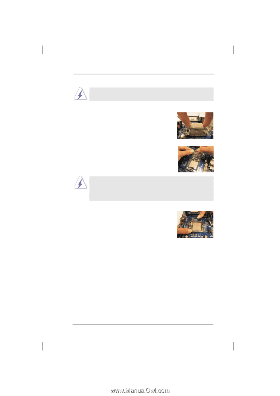
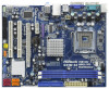
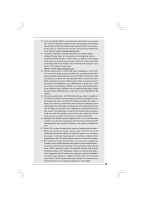
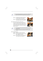
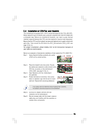
For proper inserting, please ensure to match the two orientation key notches of the CPU with the two alignment keys of the socket. Step 2-3. Carefully place the CPU into the socket by using a purely vertical motion. Step 2-4. Verify that the CPU is within the socket and properly mated to the orient keys. Step 3. Remove PnP Cap (Pick and Place Cap): Use your left hand index finger and thumb to support the load plate edge, engage PnP cap with right hand thumb and peel the cap from the socket while pressing on center of PnP cap to assist in removal. 1. It is recommended to use the cap tab to handle and avoid kicking off the PnP cap. 2. This cap must be placed if returning the motherboard for after service. Step 4. Close the socket: Step 4-1. Rotate the load plate onto the IHS. Step 4-2. While pressing down lightly on load plate, engage the load lever. Step 4-3. Secure load lever with load plate tab under retention tab of load lever. 14
-
 1
1 -
2
-
3
-
4
-
5
-
6
-
7
-
8
-
 9
9 -
 10
10 -
 11
11 -
 12
12 -
 13
13 -
 14
14 -
 15
15 -
 16
16 -
 17
17 -
 18
18 -
 19
19 -
20
-
21
-
22
-
23
-
24
-
25
-
26
-
27
-
28
-
29
-
30
-
31
-
32
-
33
-
34
-
35
-
36
-
37
-
38
-
39
-
40
-
41
-
42
-
43
-
44
-
45
-
46
-
47
-
48
-
49
-
50
 |
 |