Asus A7V600 SE Motherboard DIY Troubleshooting Guide - Page 17
Core specifications - socket 462
 |
View all Asus A7V600 SE manuals
Add to My Manuals
Save this manual to your list of manuals |
Page 17 highlights
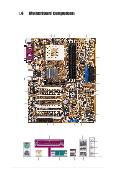
Core specifications 1 CPU socket. Socket 462 (Socket A) surface mount, Zero Insertion Force (ZIF) socket for the AMD Athlon XP/Athlon/Duron Processors. (Note: When using CPUs with FSB 100, the maximum DDR data transfer rate allowed is only at 266Mhz.) 2 North bridge controller. The VIA® KT600 supports AGP 8X mode, 400/ 333/266/200MHz Front Side Bus, and the latest 400/333/266MHz 64-bit memory bus. 3 DDR DIMM sockets. These three 184-pin DIMM sockets support up to 3GB system memory using unbuffered non-ECC PC2700/2100 DDR DIMMs. (Note: PC3200 maximum to 2 DIMMs support only. Visit the ASUS website (www.asus.com) for the latest qualified DDR400 module list.) 4 IDE connectors. These dual-channel bus master IDE connectors support up to four Ultra DMA133/100/66, PIO Modes 3 & 4 IDE devices. Both the primary (blue) and secondary (black) connectors are slotted to prevent incorrect insertion of the IDE ribbon cable. 5 ATX power connector. This 20-pin connector connects to an ATX +12V power supply. The power supply must have at least 1A on the +5V standby lead (+5VSB). 6 Floppy disk connector. This connector accommodates the provided ribbon cable for the floppy disk drive. One side of the connector is slotted to prevent incorrect insertion of the floppy disk cable. 7 AGP slot. This Accelerated Graphics Port (AGP) slot supports 1.5V AGP8X mode graphics cards for 3D graphical applications. 8 Serial ATA connectors. These two 7-pin connectors accommodate the thin cables for Serial ATA devices. 9 South bridge controller. The VIA® VT8237 integrated peripheral controller supports various I/O functions including two Serial ATA ports, 2-channel ATA/133 bus master IDE controller, up to eight USB 2.0 ports, LPC Super I/O interface, AC'97 interface and PCI 2.2 interface. 10 Super I/O controller. This Low Pin Count (LPC) interface provides the commonly used Super I/O functionality. The chipset supports a highperformance floppy disk controller for a 360K/720K/1.44M/2.88M floppy disk drive, a multi-mode parallel port, two standard compatible UARTs, and a Flash ROM interface. 11 Flash ROM. This 2Mb firmware contains the programmable BIOS program. 12 Standby power LED. This LED lights up if there is a standby power on the motherboard. This LED acts as a reminder to turn off the system power before plugging or unplugging devices. 13 USB connectors. These two 10-1 pin connectors accomodate the bundled USB 2.0 module. ASUS A7V600 SE Motherboard 1-7
-
 1
1 -
2
-
3
-
4
-
5
-
6
-
7
-
8
-
9
-
10
-
11
-
 12
12 -
 13
13 -
 14
14 -
 15
15 -
 16
16 -
 17
17 -
 18
18 -
 19
19 -
 20
20 -
 21
21 -
 22
22 -
23
-
24
-
25
-
26
-
27
-
28
-
29
-
30
-
31
-
32
-
33
-
34
-
35
-
36
-
37
-
38
-
39
-
40
-
41
-
42
-
43
-
44
-
45
-
46
-
47
-
48
-
49
-
50
-
51
-
52
-
53
-
54
-
55
-
56
-
57
-
58
-
59
-
60
-
61
-
62
-
63
-
64
-
65
-
66
-
67
-
68
-
69
-
70
-
71
-
72
-
73
-
74
-
75
-
76
-
77
-
78
-
79
-
80
-
81
-
82
-
83
-
84
 |
 |
