Asus P5GD1-VM P5GD1-VM User's manual English Edition E1881 - Page 16
Motherboard overview - lga775
 |
View all Asus P5GD1-VM manuals
Add to My Manuals
Save this manual to your list of manuals |
Page 16 highlights
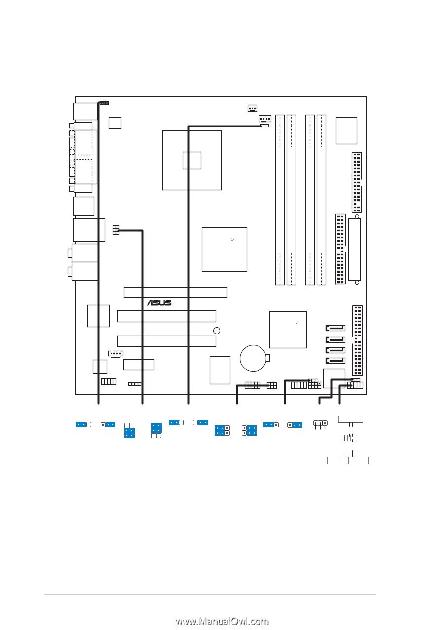
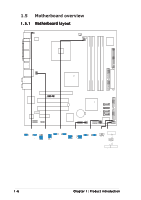
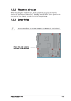
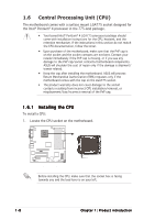
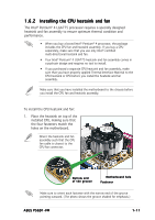
1.5 Motherboard overview 1.5.1 Motherboard layout PS/2KBMS T: Mouse B: Keyboard COM1 KBPWR1 ATX12V1 LGA775 CHA_FAN1 CPU_FAN1 FANPWR1 Super I/O DDR DIMM_B2 (64 bit,240-pin module) DDR DIMM_B1 (64 bit,240-pin module) P5GD1-VM DDR DIMM_A1 (64 bit,240-pin module) DDR DIMM_A2 (64 bit,240-pin module) PARALLEL PORT FLOPPY1 VGA1 F_USB12 USBPW34 USBPW12 LAN_USB34 Top:Rear Speaker Out Center: Side Speaker Out Below: Center/Subwoofer Top:Line In Center:Line Out Below:Mic In Kinnereth 82562EZ PCIEX16 ® PCI1 CD1 ALC880 PCI2 PCIEX1_1 AAFP1 SPDIF_OUT1 ITE 8211 Intel R 915G PRI_PCIIDE1 SB_PWR1 R Intel ICH6 SATA4 SATA3 CR2032 3V Lithium Cell CMOS Power SATA2 SATA1 USBPW56 USBPW78 CLRTC1 SPEAKER1 Intel FWH 4Mb PLED1 USB56 USB78 CHASSIS1 F_PANEL1 PRI_IDE1 EATXPWR1 KBPWR1 12 23 USBPW12 USBPW34 3 +5V +5VSB 2 2 (Default) 1 +5V +5VSB (Default) FANPWR1 12 23 PWM DC mode (Default) USBPW56 USBPW78 12 23 +5V (Default) +5VSB CLRTC1 12 23 PLED1 1 Normal Clear CMOS (Default) PLED+ NC PLED- PWR GND F_PANEL1 PWRSW IDE_LED+ IDE_LED- Ground Reset IDELED RESET * Requires an ATX power supply. 1-6 Chapter 1: Product introduction
-
 1
1 -
2
-
3
-
4
-
5
-
6
-
7
-
8
-
9
-
10
-
 11
11 -
 12
12 -
 13
13 -
 14
14 -
 15
15 -
 16
16 -
 17
17 -
 18
18 -
 19
19 -
 20
20 -
 21
21 -
22
-
23
-
24
-
25
-
26
-
27
-
28
-
29
-
30
-
31
-
32
-
33
-
34
-
35
-
36
-
37
-
38
-
39
-
40
-
41
-
42
-
43
-
44
-
45
-
46
-
47
-
48
-
49
-
50
-
51
-
52
-
53
-
54
-
55
-
56
-
57
-
58
-
59
-
60
-
61
-
62
-
63
-
64
-
65
-
66
-
67
-
68
-
69
-
70
-
71
-
72
-
73
-
74
-
75
-
76
-
77
-
78
-
79
-
80
-
81
-
82
-
83
-
84
-
85
-
86
-
87
-
88
-
89
-
90
-
91
-
92
 |
 |